PLACEMENT CONSIDERATIONS
2XWGRRU8QLW&OHDUDQFH5HTXLUHPHQWV
Minimum 12
Air inlet grille
Blown
air
Strong
wind
Strong
wind
Minimum 12
Minimum 24
Sunroof
Fence or
obstacles
Minimum 12
Air inlet grille
Blown
air
Strong
wind
Strong
wind
Minimum 20
Fence or
obstacles
Unit: Inch
Minimum 12
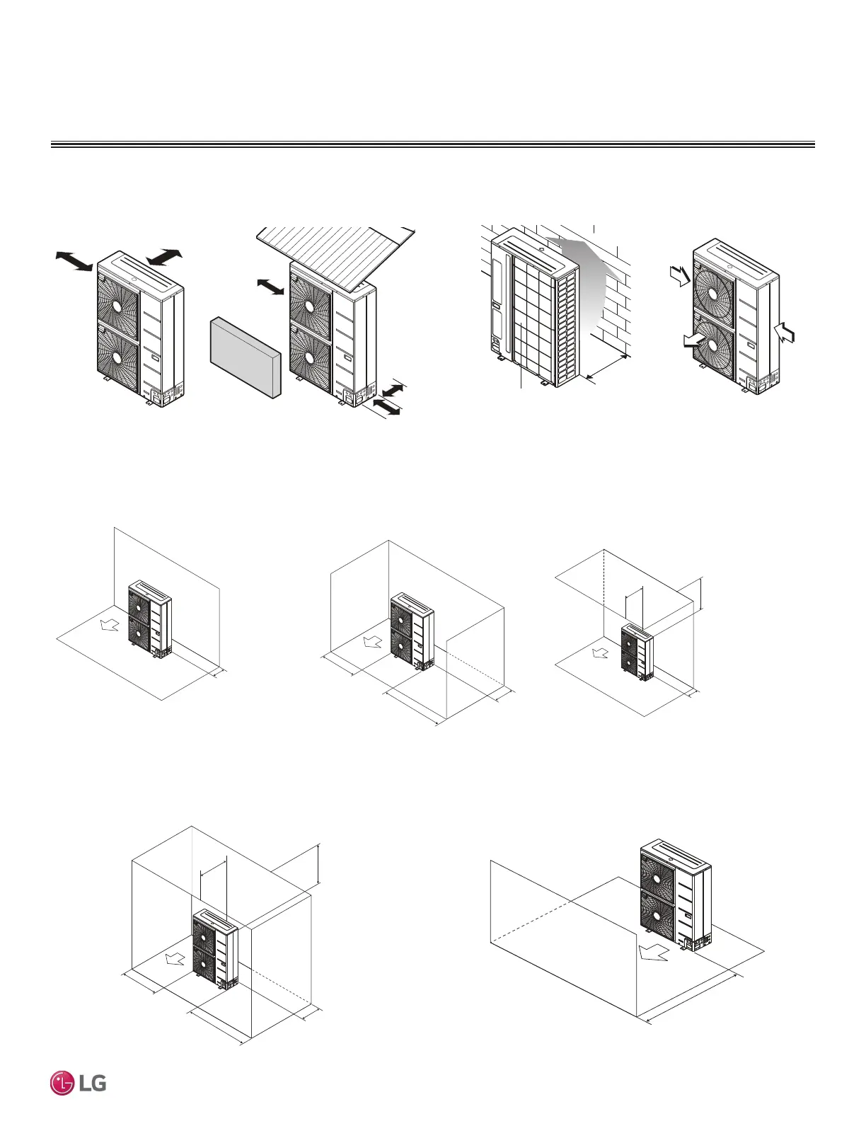
Ensure that the space at the back of the outdoor unit is a minimum of 12 inches, and
include a minimum of 24 inches at the right side of the unit for service.
If the outdoor unit discharge side faces a wall, include a minimum of 20 inches between
the outdoor unit and the wall. Install the outdoor unit so that the discharge port is set at a
right angle to the wind direction.
Multi F MAX Outdoor Unit (48,000, 54,000 and 60,000 Btu/h Capacity) Service Access and Allowable Clearances
When installing the outdoor unit, consider service, inlet, and outlet, and minimum allowable space requirements as illustrated in the following
diagrams.
Clearance Requirements when Different Obstacles are Present (Unit: Inch).
Minimum 12"
Minimum 20"
Minimum 40"
Obstacles above and on the air intake side
Minimum 12"
Maximum 20
"
Minimum 12"
Minimum 40"
Minimum 24"
Obstacles above, on the air intake side,
and on both left and right sides
Minimum 20"
Obstacle just on the
air discharge side.
Minimum 12"
Minimum 12"
Minimum 12"
Minimum 24"
Obstacle on the suction side only. Obstacles on the suction side and
on both left and right sides.
'XHWRRXUSROLF\RIFRQWLQXRXVSURGXFWLQQRYDWLRQVRPHVSHFL¿FDWLRQVPD\FKDQJHZLWKRXWQRWL¿FDWLRQ
©/*(OHFWURQLFV86$,QF(QJOHZRRG&OLIIV1-$OOULJKWVUHVHUYHG³/*´LVDUHJLVWHUHGWUDGHPDUNRI/*&RUS
PIPING AND PLACEMENT | 69
Piping Limitations and Placement Considerations
MULTI
F
MAX
MULTI
F
 Loading...