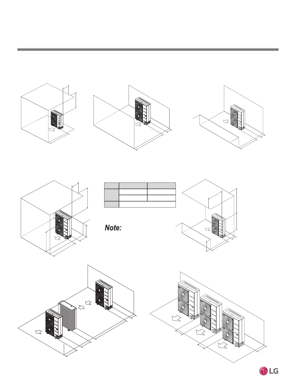
PLACEMENT CONSIDERATIONS
2XWGRRU8QLW&OHDUDQFH5HTXLUHPHQWV
Where there are obstacles on both suction
and discharge sides (discharge side obstacle
is higher than the outdoor unit).
Minimum 20"
Minimum 12"
Table 38: Ratio among H, A, and L.
Clearance Requirements when Different Obstacles are Present, continued. (Unit: Inch)
If a stand is necessary, it must be contained (not open
frame) to prevent the discharge air from short cycling.
LA
/+
/+ 30 inches
1/2 H < L 40 inches
H < L
6HW6WDQGDV/+
Where there are obstacles above, and on both
suction and discharge sides (discharge side obstacle
is higher than the outdoor unit).
Maximum 20"
Minimum 12"
Minimum 40"
L
H
A
L
Minimum 40"
Minimum 40"
Maximum 20"
Minimum 12"
Where there are obstacles above, and on both
suction and discharge sides (discharge side obstacle
is lower than the outdoor unit).
H
Minimum 12"
Minimum 79"
Minimum 24"
Minimum 40"
Series installation
“L” must be lower than “H”. If a stand
is necessary, it must be contained (not
open frame) to prevent the discharge air
from short cycling.
Where there are obstacles on both suction
and discharge sides (discharge side obstacle
is lower than the outdoor unit).
Minimum 20"
Minimum 12"
Minimum 20"
Minimum 20"
Minimum 40"
Obstacles above and on the
air discharge side.
Minimum 12"
Minimum 24"
Minimum 24"
Side-by-side series installation.
'XHWRRXUSROLF\RIFRQWLQXRXVSURGXFWLQQRYDWLRQVRPHVSHFL¿FDWLRQVPD\FKDQJHZLWKRXWQRWL¿FDWLRQ
©/*(OHFWURQLFV86$,QF(QJOHZRRG&OLIIV1-$OOULJKWVUHVHUYHG³/*´LVDUHJLVWHUHGWUDGHPDUNRI/*&RUS
70 | PIPING AND PLACEMENT
Multi F and Multi F MAX Heat Pump System Engineering Manual
MULTI
F
MAX
MULTI
F
 Loading...