20
2 - INSTALLATION
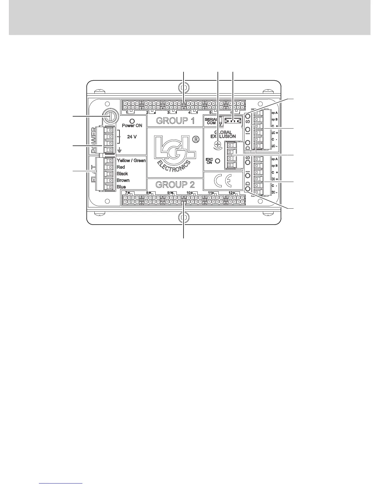
1. POWER (power supply connector)
There are 3 different ways to feed voltage to LGL box:
− 18Vac to 28Vac single phase alternating voltage.
Connect the two (single-phase) lines between two phases whatsoev-
er (a, b or c) of the POWER connector.
− 18Vac to 28Vac three-phase alternating voltage.
Connect the three (three-phase) lines into 3 (a, b and c) phases of the
POWER connector.
− 23Vdc (*) to 40 Vdc direct voltage
Connect the two (DC power supply) lines between
2 phases whatsoever (a, b or c) of the POWER connector.
Connect the earth-fault protection cable into the clamp marked with the
electrical earth symbol.
(*) N.b.: The minimum power supply value of the box is 23Vdc, 1V high-
er than that of the devices to compensate for the voltage drop
on external diodes.