21
2 - INSTALLATION
2. FLAT: connector for flat cable.
1 - Yellow/Green –0V (GND) power supply.
2 - Red – power supply (22Vdc to 40Vdc) for flat cable connected de-
vices.
3 - Black – Stop signal.
4 - Brown – CANL / LSB serial communication.
5 - Blue – CANH / LSA serial communication.
3 & 4. Connectors (group 1 & group 2) for single cable. Available for up to
12 accumulators.
The position will automatically assign the address to the device (1 to 12).
5. Stop and INC & DEC signals referred to accumulators connected
to group 1 connectors.
6. Stop and INC & DEC signals referred to accumulators connected
to group 2 connectors.
Notes for INC and DEC signals:
- Power supply for INC and DEC signals from 5Vdc to 40 Vdc
from 12Vac to 28Vac
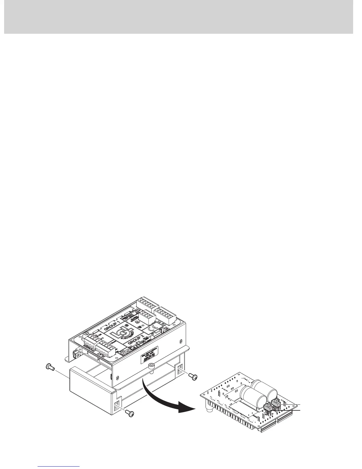
- Stop signals: STOP A= N.O. STOP B = COM. Dry contacts.
N.O. / N.C. programmable via Dip Switches SW2 – SW3 located un-
der the board. To access the Dip Switches you need to de-energize
the box, unscrew the 4 screws that fasten the base and the lid and
separate them.