42
SWITCH 1: STOP SIGNAL POLARITY
0 = NO 1 = NC
If set to 1, the STOP signal signalling logic is reversed.
AO-1 – STOP POLARITY = 0
AO-1 – STOP POLARITY = 1
SWITCH 2: INC/DEC GRADUATION RESET
0 = T1 ➝ T2
1 = SEE PROCEDURE
INC & DEC graduation reset mode.
PROCEDURE:
STOP
1 = STOP ENABLED
0 = STOP INHIBITED
STOP
1 = STOP INHIBITED
0 = STOP ENABLED
AO-2
- INC/DEC
GRADUATION
RESET= 0
Graduations are reset while moving from T1 to T2.
N.b.: If T2 is “OFF” the reset takes place al the same when the
INC/DEC signals switch from ON to OFF. Or from OFF to ON if the
“AO-0 - INC/DEC SIGNAL POLARITY” option is set to 1.
AO-2
- INC/DEC
GRADUATION
RESET = 1
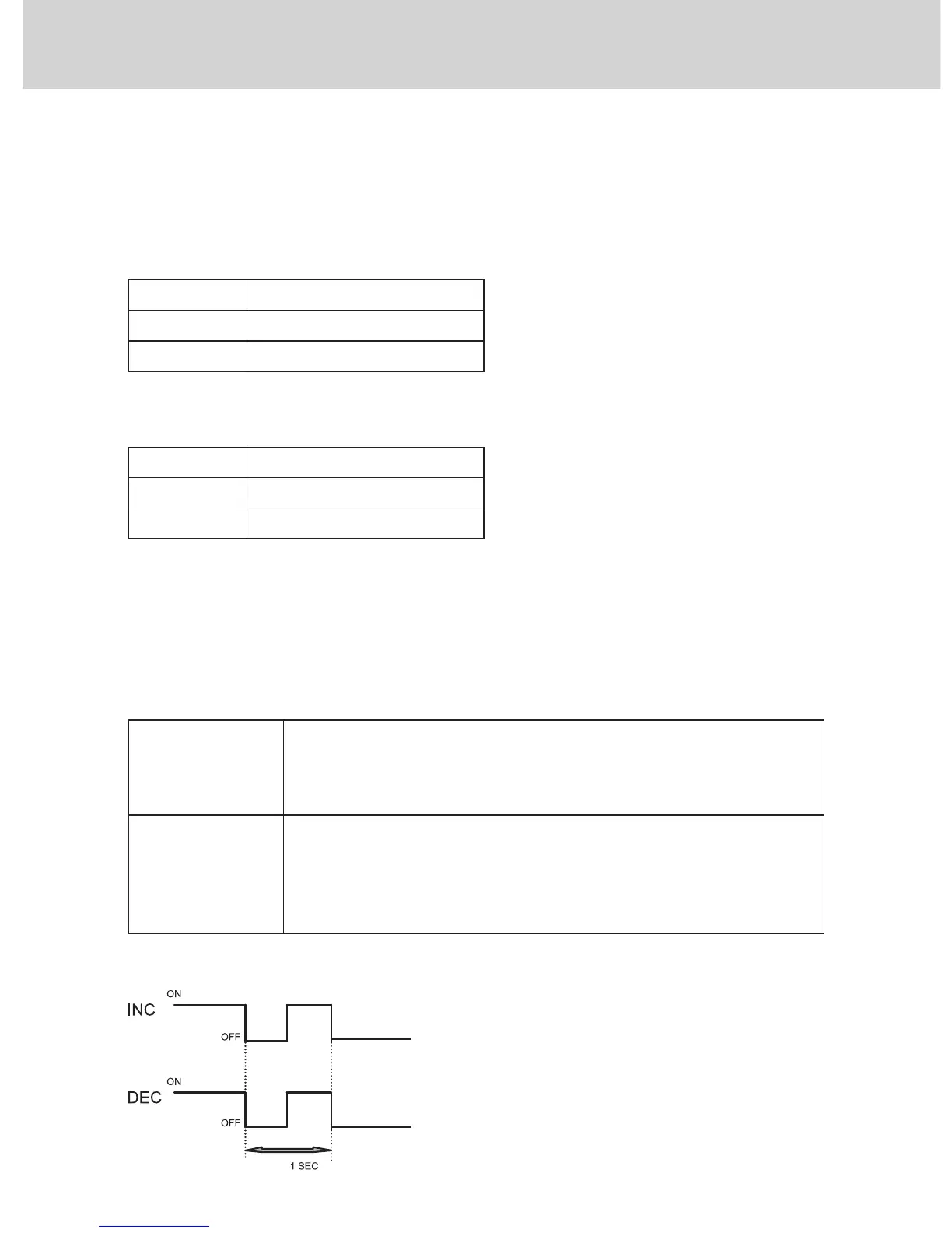
Graduations are only reset via the special timed sequence.
The sequence consists in setting both the INC and DEC signals to OFF,
then to ON and finally back to OFF, within a time not greater than 1 se-
cond. N.b.: please bear in mind that if the “AO-0 - INC/DEC SIGNAL
POLARITY” option is set to 1, the sequence logic is reversed.
4 - SETTING THE OPERATING PARAMETERS