Step-by-Step Calibration Instructions
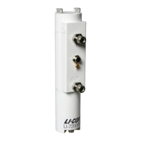
Figure 4-1. Flow calibration gas into the
Air IN port. Be very careful to not dam-
age the inlet thermocouple when con-
necting the tubing. Attach 15 cm (6 in.)
of tube to the outlet to prevent diffusion
of ambient air into the analyzer.
1
Clean the optical cell and reassemble it (see
Cleaning the Optical Path on page5-3).
2
Disconnect the intake tube at the air inlet on the
sensor head.
3
Connect the calibration gas to the air inlet fitting
using 3/8” I.D. Bev-a-line tubing, or with ¼” I.D.
Bev-a-line tubing and the 3/8-1/4” adapter.
Do not try to insert ¼” Bev-a-line or
other small diameter tubing into the air
IN or air OUT fittings, as you can break
the fine-wire thermocouples in each of the
fittings.
4
Flow CO
2
-free air at a rate of about 0.5 to 1.0
LPM or more.
Attach the zero gas to the air IN fitting.
Note the position of the ferrules inside
the fitting. When you tighten the fitting,
the ferrules will compress slightly to hold
the tubing in place.
Section 4. User Calibration
4-5Checking the Span
 Loading...