Do you have a question about the LI-COR LI7200RS and is the answer not in the manual?
Verifies that all ordered components for the LI-7200RS have been received.
Details the contents of spare parts kits for the sensor head and interface unit.
Describes power, sensor head, Ethernet, and RS-232 cables for system connection.
Provides calibration coefficients for the sensor head, unique to each unit.
Explains the SmartFlux 2 System standard component for flux processing.
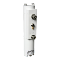
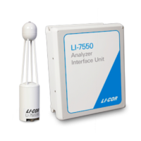
Details the LI-7550 unit housing analyzer electronics and USB port.
Covers basic steps for setting up the LI-7200RS analyzer.
Describes how to install the instrument and associated components.
Details the use and customization of the insulated intake tube.
Explains the installation and function of the heated intake tube accessory.
Provides guidance on mounting the sensor head and intake tube assembly.
Details the correct procedure for connecting the sensor head cable.
Offers advice for optimal performance and maintenance.
Advises on adjusting settings for cold weather operation.
Discusses precautions for operating in extremely humid conditions.
Explains the setup and connection of the ASI for sensors.
Details the pin assignments for analog inputs and outputs on the ASI.
Describes ground referencing and isolation for ASI connections.
Instructions for downloading and installing the LI-7200RS software.
Guides on establishing communication between PC and analyzer.
Details connecting the instrument via RS-232 serial port.
Overview of the dashboard for configuration and status monitoring.
Presents information on the analyzer's status and logging capabilities.
Explains how to interpret instrument status and connectivity indicators.
Describes how to view real-time and processed flux data graphically.
Explains how to change and select variables for display.
Guides on setting up eddy covariance system parameters.
Details on setting the instrument's time and date synchronization.
Inputting site-specific information for metadata.
Configuring anemometer details for data acquisition.
Setting analyzer position relative to the sonic anemometer.
Describes how to configure the 7200-101 Flow Module.
Guides on setting the power setpoint for the heated intake tube.
Steps to connect and log data from an LI-7700 CH4 Analyzer.
Explains how to connect LI-COR or Biomet dataloggers.
Guides on connecting to SmartFlux systems for data processing.
Details Express and Advanced modes for EddyPro data processing.
Instructions for starting and stopping data logging.
Explains the structure and compression of data files.
Describes methods for downloading and managing logged data.
Discusses factors affecting the stability of zero and span readings.
Step-by-step guide to setting the zero point for CO2 and H2O.
Procedure for setting the span for CO2 and H2O measurements.
Detailed instructions for performing zero and span calibrations.
Procedure for zeroing the CO2 measurement.
Procedure for zeroing the H2O measurement.
Procedure for setting the CO2 span.
Procedure for setting the H2O span.
Guidance on setting a secondary span for CO2.
Guidance on setting a secondary span for H2O.
Explains the underlying calculations for zero and span.
Provides a schedule for routine site maintenance tasks.
Monthly maintenance tasks including checks and data backup.
Instructions for cleaning the analyzer's optical windows.
Steps for safely accessing the optical bench for cleaning.
Procedure for replacing the scrubbing chemicals.
Guide for cleaning the intake cap and screen assembly.
How to monitor and clean the intake filter.
Instructions for checking and replacing fuses in the LI-7550.
Procedure for replacing air temperature thermocouples.
Steps to perform a leak test on the sensor head.
Information on updating embedded and Windows interface software.
Detailed steps for updating the analyzer's embedded software.
Routine maintenance procedures for the flow module.
Addresses issues where the software misidentifies the analyzer model.
Troubleshooting steps for power-related issues.
Common issues encountered with the SmartFlux 2 System.
Troubleshooting network and firewall issues.
Resolving issues with serial communication.
Steps to take when the instrument software becomes unresponsive.
Diagnosing and resolving incorrect temperature readings.
Troubleshooting incorrect pressure readings.
Resolving issues with inaccurate CO2 or H2O measurements.
Tips for reducing noise in measurement readings.
Overview of instrument settings configuration.
Setting the instrument time and date using PTP.
Configuring clock synchronization and time zone settings.
Configuring network settings, including IP addresses.
Manually entering IPv4 address or Hostname.
Setting up port forwarding for network access.
Using the command line for instrument control and diagnostics.
Adjusting chopper housing temperature for power and performance.
Setting up integration functions for CO2 measurements.
Overview of the LI-7200/RS software menu structure.
Configuring auxiliary input channels for sensors.
Configuring analog output channels, RS-232, Ethernet, and SDM.
Setting RS-232 port configuration for unattended data collection.
Configuring instrument's Ethernet port for network communication.
Configuring DAC output channels for analog signals.
Configuring SDM output for Campbell Scientific dataloggers.
Setting output delay times for synchronization.
Examples illustrating total system delay calculations.
Determines signal averaging and affects aliasing.
Interpreting the 2-byte diagnostic value bitmap.
Overview of the calibration window for zero and span settings.
Resets signal strength and provides information on optics cleanliness.
Displays factory-determined calibration coefficients.
Displays current zero and span values.
Lists previous calibration backup files.
Procedure for replacing sensor heads with calibration updates.
Configuring data output parameters for logging to a PC.
Instructions for starting, stopping, and ejecting USB log files.
Viewing current operational state and diagnostic flags.
Interpreting diagnostic indicators like Sync Flag, PLL, and Detector Temp.
Displays voltages and raw counts of diagnostic test points.
Displays the current state of the analyzer's chopping shutter disk.
Allows real-time graphics display of variables against time.
Storing and managing instrument configuration settings.
Explains the scaling law relating pressure and infrared absorption.
Describes how to determine absorptance from radiant power.
Discusses cross-sensitivity between gases and its software correction.
Explains detector temperature drift and software fine-tuning.
Summarizes the fundamental equations used in calculations.
Lists fundamental equations used in LI-7200RS calculations.
Discusses the impact of pressure and temperature on measurements.
Explains how to use raw reference signals for diagnostics.
Uses signal strength difference to indicate calibration drift.
Details DSP bandwidth and frequency response.
Lists measurement specifications for CO2.
Lists measurement specifications for H2O.
Provides general specifications like sampling rate and bandwidth.
Details pin assignments for SDM, Auxiliary Input, and DAC Output.
Describes the RS-232 serial pin-out and wiring.
Lists suppliers for chemical scrubbing materials.
Information on purchasing pre-charged internal chemical bottles.
Lists available cables and their part numbers.
Information on compatible industrial-grade USB drives.
Defines the command structure for configuring data output.
Identifies commands sent by the instrument and their formats.
Provides a summary of command abbreviations and structures.
Describes methods for querying instrument data.
Command for scaling auxiliary input channels and measuring pressure/temperature.
Commands for controlling zeroing, spanning, and calibration coefficients.
Command to reset the instrument software.
Command for configuring network settings.
Command for setting system date, time, and PTP.
Commands for configuring and reading flow module parameters.
Command to query instrument configuration parameters.
| Gas Measured | CO2 and H2O |
|---|---|
| Accuracy CO2 | ± 1.5% of reading |
| Accuracy H2O | ± 2% of reading |
| Measurement Principle | Non-Dispersive Infrared (NDIR) |
| Operating Humidity Range | 0 to 100% RH (non-condensing) |
| Outputs | Analog |
| Measurement Range CO2 | 0 to 3000 µmol/mol |