Do you have a question about the Liberty Pumps LCU-PR20S and is the answer not in the manual?
Please read, understand, and follow all safety instructions. Failure to follow instructions may result in property damage, serious injury, or death.
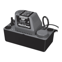
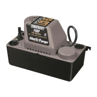
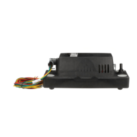
Lists the parts included in the package, such as the condensate pump and inlet hole covers.
Provides technical details for LCU-PR20S and LCU-PR220S models, including voltage, current, head height, and flow rate.
Determine condensate pump location. Pump must be level and should be mounted to, or placed on, a solid surface or floor away from moving objects and extreme heat.
Attach condensate pump with screws, through mounting tabs (8" between mounting tabs).
Ensure that condensate pump is level. Unit out of level by more than 15° may not function properly and voids warranty.
Attach plastic tubing to check valve and secure with hose clamp. Route tubing up and away from pump.
Install condensate drain tubing into one of the four inlet holes, making sure tubing is vertical. Cut tubing to 45 degree angle.
Insert inlet covers in remaining condensate pump inlet holes.
Connect conduit fitting, route wires, and secure conduit into fitting. Ream conduit to prevent wire abrasion.
Connect safety switch to Class II Low Voltage circuit, normally closed. Disconnect power before modifying.
Manually fill tank to test float operation and LED indicators. Overfill to test overflow switch functionality.
Explains the meaning of Green, Amber, and Red LEDs indicating power, running, and alarm conditions.
| Model | LCU-PR20S |
|---|---|
| Voltage | 115 V |
| Flow Rate | 20 GPM |
| Max Head | 20 ft |
| Cord Length | 10 ft |
| Hertz | 60 Hz |
| Phase | Single |
| Motor Type | Permanent Split Capacitor (PSC) |
| Housing Material | Thermoplastic |
| Switch Type | Automatic |
| Seal Material | Ceramic/Carbon |
| Pump Type | Submersible |
| Type | Submersible |