6
TOP---UPS OF UP TO 20---30% OF THE TOTAL AMOUNT OF
OIL CONTAINED IN THE COMPRESSOR CRANKCASE ARE
PERMITTED; FOR LARGER PERCENTAGES CONTACT THE
TECHNICAL SUPPORT DEPARTMENT.
5.2.1 -- Procedure for o il topping--up
If there has been any loss of oil then this must be topped up as
follows:
1) Take a clean, dry, transparent container (with volume cal-
ibrations) and fill it with at least twice the amount of oil re-
quired.
2) Isol ate the compressor by closing the cock on the liquid line.
3) Connect to the fittings on the compressor body (Schraeder
valves) and empty it of refrigerant until atmospheric pres-
sure (1 bar) is reached.
4) Using a pipe, connect t he oil containerto theoil s er vic efitting
on the lower part of the compressor.
5) Open the oil service cock, lifting the co ntainer, so that the oil
flows by gravity.
6) Charge the required quantity of oil (make sure the tube al-
ways remains below the oil level in the container).
7) Stop the oil flow by closing the oil service fitting, open the
shut---off cock on the refrigerating circuit and restore the
drained refrigerant charge.
6 --- Safety Devices Settings
The water chiller has already been tested and set up by the manufacturer. The following setting values are suggested in the field.
COMPONENT SETTING NOTES
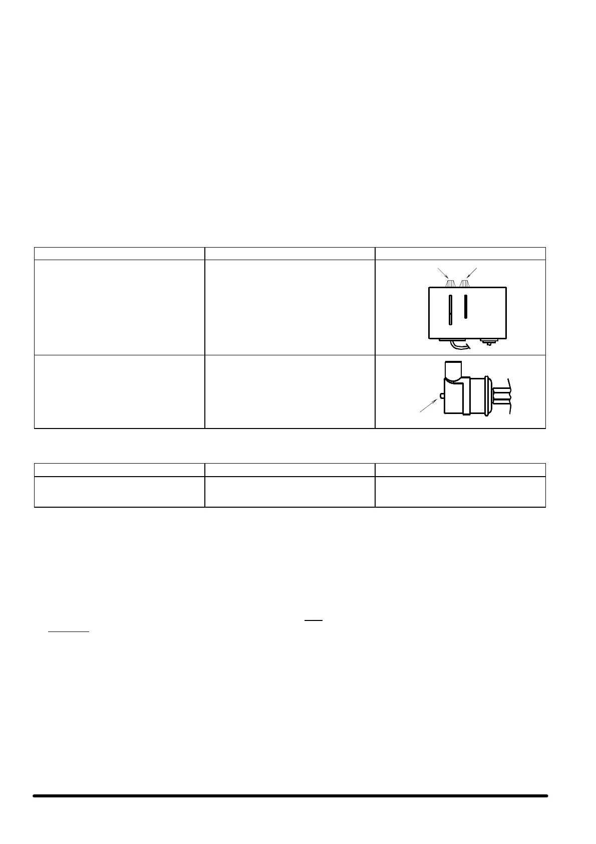
Low pressure switch (LP)
Operation with R407C/R22
(standard factory setting):
START : 3.6 bar
DIFF. : 0.8 bar
STOP : 2.8 bar
bar
5
0.2
1.5
0.5
bar
diff.set
High pressure switch (HP)
Operation with R407C/R22
(standard factory setting):
STOP : 26 bar
START : 20 bar
DIFF. : 6 bar (fixed)
reset
The settings for the safety valves installed on the machine are indicated below:
MODELS SETTINGS SAFETY VALVE
CBH/CLH/CQH 017---020---023---025---028
SBH/SLH 017---020---023---025---028
SQH 017---020---023 ---025
29 bar high pressure side
6.1 --- Setting the rmostatic ex pansion
valve
THIS OPERATION MUST BE PERFORMED BY AN EXPERI-
ENCED REFRIGERATION TECHNICIAN.
Before beginning this adjustment be sure that the refrigerant
charge is correct, checking the the sub ---cooling (3ûC --- 5ûC, as
specified in par. 5.1).
The valve has already been factory --- set and should be reset
when the superheating is not between 5ûC --- 8 ûC, as follows:
1) Important:
Ensure that the instructions in par. 5.1 have been carried out.
2) Allow the compressor to operate for 15 mins.
3) Measur e the superheating as follows:
a) Connect a manometer to the Schraeder connect io n lo-
cated on the evaporator outlet tube, and read the mano-
metric temperature on the scal e for the refrigerant used
(for the units with R407C refer to the pressure gauge
scale indicated with the initials D.P. = Dew Point).
b) Using a cont act thermometer, measure the temperature
on the tube coming out of the evaporator, next to the
socket used for the manometer.
c) The superheating is the difference between the two
readings (b ---a).
4) The superheating must be 5ûC --- 8 ûC; if not, set the expan-
sion valve as follows:
a) Remove the protective cover;
b) Turn the adjustment screw to return to the optimum val-
ues, tightening it in a clockwise directio n to increase the
superheating, or slackening it to reduce the superheat-
ing.
c) Wait about 10 minutes;
d) Measure the superheating and repeat the operation if
necessary.
N.B:
If the superheating is too low, there is a risk of poor lubrication
and consequent breakage of the compressor as a result of pres-
sure shock.
If the superheating is too high the output of the syst em is limited
and the compressor overheats.