System Performance with Advanced Microprocessor Controls
35
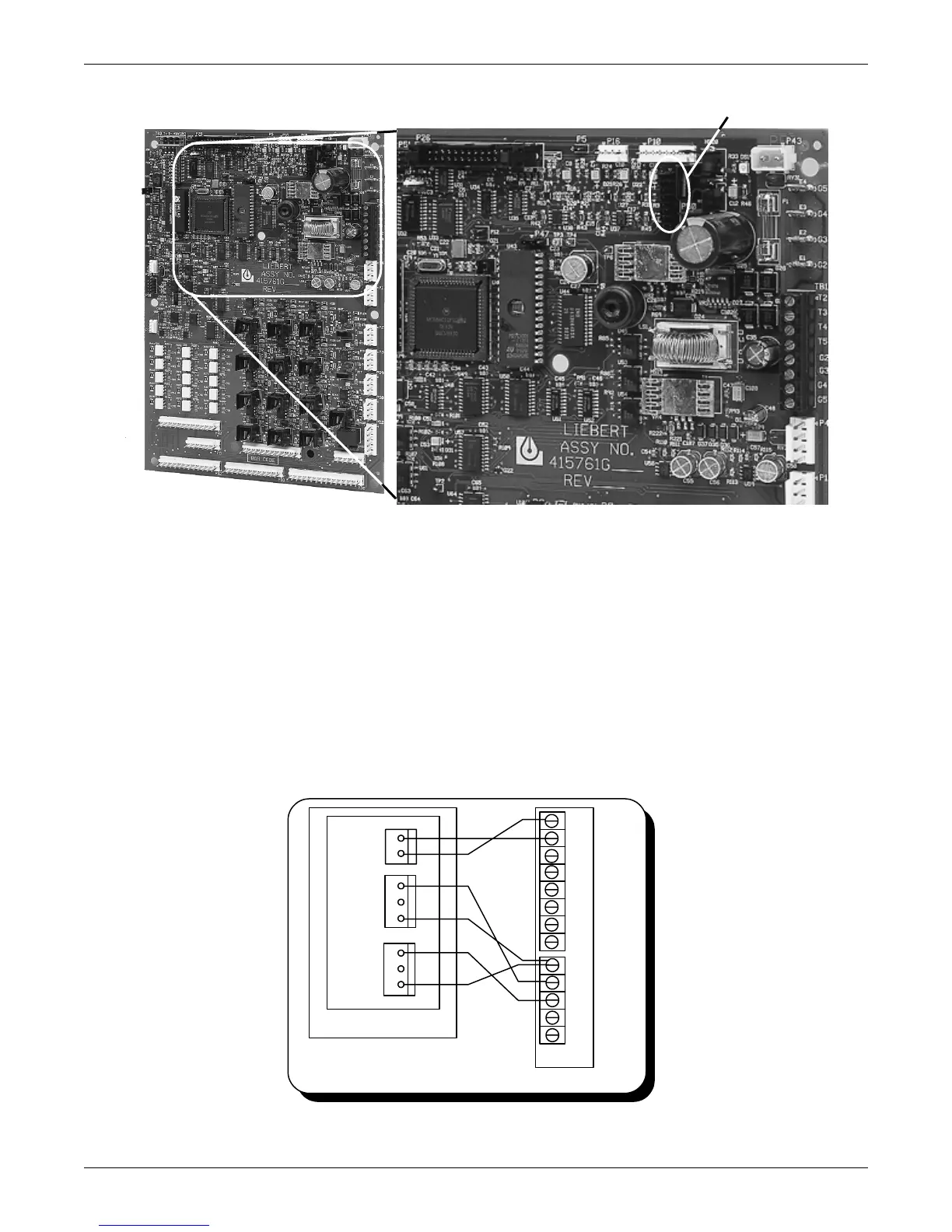
Figure 5 Analog input jumpers
4.5.2 Water Detection Display
The water detection display is designed to graphically display the location of water under a raised
floor when connected to an LT750 water detection system. The graphical floor plan screen shows a 30
x 16 grid. Each square represents one standard floor tile (approximately 2 ft. x 2 ft.).
Installation—LT750 DIP Switch Settings
Install the LT750 following the instructions in the LT750 user manual. The following additional
switch selections should be made when connecting to an Advanced Microprocessor control:
• DIP SW3-4—Off-(water alarm relay energizes for alarm)
• DIP SW3-5—Off-(cable fault relay energizes for alarm)
• Switch 1—Off-(LT750 sources power for 4-20 mA loop)
Figure 6 Connecting the LT750
Analog input jumper location
ENLARGED AREA
TB4
water
TB5
fault
LT750 Environmental Unit
3
2
1
3
2
1
2
1
+
NO
4 1
4 2
4 3
4 4
4 5
4 6
4 7
4 8
2 4
5 0
5 1
5 5
5 6
TB6
-
C
NC
NO
C
NC