Do you have a question about the Liebert CR020 and is the answer not in the manual?
Details hazards and precautions related to electrical shock.
Highlights dangers of high-pressure refrigerant discharge.
Warns about hazards of overpressurization in refrigerant systems.
Guidelines for checking delivered equipment upon arrival.
Safe procedures for moving and handling the unit.
Defines the acceptable operating and storage conditions.
Information on the sound pressure levels emitted by the unit.
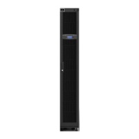
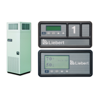
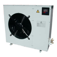
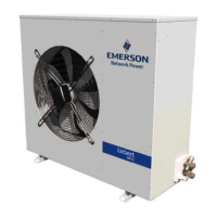
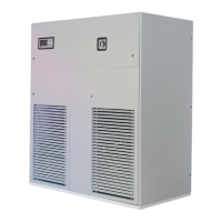
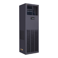
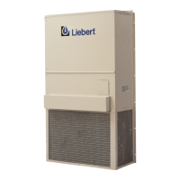
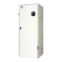
Overview of unit appearance and typical installation scenarios.
Best practices for positioning units relative to server racks.
Guidance on matching unit capacity to rack load and row length.
Optimizing aisle width and ensuring adequate clearances for airflow.
Implementing N+1 redundancy for continuous cooling.
Using CoolFlex and Liebert XD with CRV units.
Reference guide for receiving and preparing unit for installation.
Safe procedures for handling packaged units during transport.
Step-by-step guide for safely unpacking the air conditioner.
Procedures for unit installation, leveling, and baffle adjustment.
Details on connecting refrigerant lines for air-cooled models.
Steps for evacuating the system and charging refrigerant.
Reference to refrigeration circuit diagrams and component functions.
Advice on adding glycol for outdoor tubing to prevent freezing.
Connecting water lines for humidifier supply and condensate drain.
Connecting water/glycol circuits for W unit models.
Connecting chilled water circuits for C unit models.
Guidelines for routing and connecting electrical cables to the unit.
Overview of built-in protection mechanisms for EC fans.
Details on safety features and reset procedures for electrical heaters.
Guidelines for positioning temperature sensors for accurate readings.
Steps for initial unit start-up or after extended periods of inactivity.
Configuration and behavior of the automatic restart feature.
Procedure for verifying pressure drops in refrigerant lines for performance.
How to control and verify the operation of the chilled water valve.
Explanation of direct expansion and chilled water cooling operations.
How the heating elements function to warm the air.
Mechanism and control logic for removing humidity from the air.
How the humidifier creates and distributes steam into the airflow.
Procedure for adjusting the thermostatic expansion valve for optimal superheat.
Optimal placement of sensors to avoid false alarms.
How calibration impacts energy efficiency and environmental protection.
Essential safety precautions for all maintenance activities.
Recommendations for using original spare parts to maintain warranty.
Detailed schedule of monthly, quarterly, biannual, and annual checks.
Procedure for checking and replacing air filters for optimal airflow.
Procedures for cleaning and maintaining condensate drainage components.
Steps for cleaning external heat exchange coils.
Inspection and cleaning procedures for electrical heating elements.
Procedures for servicing the unit's refrigeration components.
Guidelines for safely dismantling the unit at end-of-life.
Information on regulations concerning fluorinated greenhouse gases.
Table of common problems, their causes, and corrective actions.
Introduction and technical data for the integrated humidifier.
Connecting water supply and drain lines for the humidifier.
Description of humidifier parts and how it operates.
Steps for removing, replacing, and annual servicing of the humidifier.
Guidance on ordering and replacing humidifier spare parts.
Diagrams and specifications for air-cooled unit connections.
Diagrams and specifications for water-cooled unit connections.
Diagrams and specifications for chilled water unit connections.
Details on electrical connections, cable entry, and terminal blocks.
Information on optional electrical connections and their functions.
Details on connections used for maintenance operations.
Detailed wiring schematic for the CR020 model.
Detailed wiring schematic for the CR035 model.
Detailed wiring schematic for the CR040 model.
| Brand | Liebert |
|---|---|
| Model | CR020 |
| Category | Air Conditioner |
| Language | English |


 Loading...