Appendix 6 Wiring Diagram 67
Liebert.CRV Series Air Conditioner User Manual
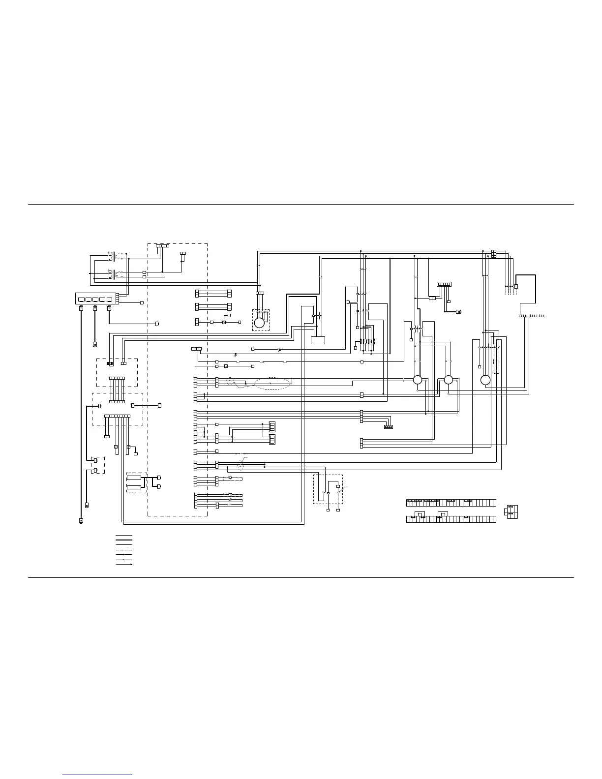
Appendix 6 Wiring Diagram
380V~415V/50Hz 3N~
L2
BK
BK
3
4
L1
1
2
BK
NL3 PE
6
5
8
7
PE
Main switch
QS
2 4
BK
BK
1
Fan breaker
QF1
~
A1
A2
2
1
4
3
6
5
1
4
1
3
3
~
2 4 6
BK
BK
BK
1 5
Heater breaker
QF5
A1
A2
2
1
4
3
6
5
14
13
3
A1
A2
2
1
4
3
6
5
2 4
BK
BK
1
Humidifier
breaker
QF7
A1
A2
2
1
4
3
6
5
3
LN -+ PE
AC/DC Supply unit
AL
2 4
BK
BK
1
Transformer
breaker
QF8
3
PE1
Fan contactor
KM1
FAN1-NC
FAN1-COM
YE
BL
FAN2-NC
00
Y1
P5
710
054
i-COM
A1
Heat contactor1
KM6
Humidifier
contactor
KM7
0
24
ST13-C ST13-NC
Thermostat
P2
1 2 3 4
ST12-C ST12-N C
Manual Thermostat
0
0
Door switch1
Door switch2
Door switch3
52
53
63
62
P8
84
83
82
81
Delivery air probe
P10
NC
NOCF-COM
Clogged filter alarm
106
105
Water under floor switch
1
2
3
4
1
2
3
4
5
6
1
2
3
4
P7
1
2
3
4
P14
1
2
3
4
P12
1
2
3
4
5
6
7
8
P6
1
2
3
4
P17 1
2
G0
Y2
24
YG G0
Condensing water valve
71
70
Connection bars
QS-7
XP-1
FAN2-COM
XP-3
XP-5
BK
BK
TB-70
TB-71
TB-24
TB-G0
TB-Y2
TB-00
TB-Y1
TB-710
TB-054
CWV-G
CWV-G0
CWV-Y
QS-5
QS-3
QS-1
PE1
QF1-2
QF1-4
KM1-1
KM1-5
KM1-A1
KM1-13
KM1-2
KM1-6
KM1-14
KM1-A2
Y/GN
FAN1-L
XPE
AL-N
AL-L
AL-PEXPE
QF5-2
QF5-4
QF3-6
KM6-1
KM6-3
KM6-5
KM6-2
KM6-4
KM6-6
KM5-1
KM5-3
KM5-5
KM5-A1
KM5-A2
KM6-A1KM6-A2
KM5-13KM5-14
KM5-2
KM5-4
KM5-6
TB-0
EH-1
EH-3
EH-5
EH-2
EH-4
EH-6
EH-N1
EH-N3
EH-N5
EH-N2
EH-N4
EH-N6
QF7-2
QF7-4
KM7-A1
KM7-1
KM7-5
KM7-A2
KM7-2
KM7-6
SL A D
HUM-SL
HUM-A
HUM-D
BK
BK
QF8-2
QF8-4
R8 S8
TB-R8
TB-S8
BK
BK
A1-P2-4
A1-P2-3
BK
TB-52
TB-53
TB-62
TB-63
TB-81
TB-82
TB-83
TB-84
TB-105
TB-106
A1-P5-1
A1-P5-2
A1-P5-3
A1-P5-4
A1-P7-1
A1-P7-2
A1-P7-3
A1-P7-4
A1-P14-1
A1-P14-2
A1-P14-3
A1-P14-4
A1-P6-1
A1-P6-2
A1-P6-3
A1-P6-4
A1-P8-1
A1-P8-2
A1-P8-3
A1-P8-4
A1-P10-3
A1-P10-4
A1-P10-5
A1-P10-6
MP1-NO MP1-C MP2-NO MP2-C MP3-NO MP3-C
50
TB-50
19
TB-19
1 2
CF-NC
COM
PE9
TB-R8
TB-S8
TB-PE9
BK
Y/GN
Y/GN
Y/GN
BK
BK
BK BK
BL
BK BK
BK
BK
BK
BK
BK
BK
BK
BK
BK
BK
BK
BK
BK
BK
BK
BK
BK
BK
BK
BK
BK
BK
BK
Humidifier
Heat
contactor2
KM5
Fan1
Fan2
XPE
FAN1-N
FAN2-L
FAN2-N
1
3
5
2
4
6
XP
ALL+
AL-L-
Remote ON/OFF
Fire sensor
51
54
TB-51BK
TB-54
BK
61
TB-61 BK
BK
TB-U01
U02
TB-U02
U01
XPE
XPE
XPE
XPE
LWD
Remote display cable supply
Condensate
pump
~
BR
BR
P P
Optional
P1 1 2 3 4 5
24
0
P3 1 2
Etherent switch
A1-P1-1
A1-P1-2
A1-P1-3
A1-P1-4
A1-P3-1
A1-P3-2
TB-24
TB-0
BK
BK
BK
BK
6 5 4 3 2 1
P3 P4
Isolation board
A6
P1
TAM
BK BK
A6-P3
A6-P4
P64
A1-P64
A3
Humidification control board
A5
1 2 3 4 5 6P1
1 2 3 4 5 6P2 7 8 9 10
24 0
XPE
Drain
solenoid
valve
P66 P67
A6-P1-6
A6-P1-5
A6-P1-4
A6-P1-3
A6-P1-2
A6-P1-1
A5-P1-1
A5-P1-2
A5-P1-3
A5-P1-4
A5-P1-5
A5-P1-6
A5-P2-1
A5-P2-2
A5-P2-5
A5-P2-6
A5-P2-7
A5-P2-8
A5-P2-9
A5-P2-10
TB-24
TB-0
XPE
A5-P66 A1-P67
BK
BK
BK
BK
BK
BK
BK
BK
BK
BK
BK
BK
BK
BK
YV07-2YV07-1
YV7-2YV7-1
Charge
solenoid valve
THB
1
401
400
402
301
300
302
2
3
1
2
3
TB-400
TB-401
TB-402
TB-300
TB-301
TB-302
A1-P16-1
A1-P16-2
A1-P16-3
A1-P15-1
A1-P15-2
A1-P15-3
BK
BK
BK
BK
BK
BK
P16
P15
1
2
3
P4
Remote-DIS
A1
A2
14
11
12
0
395
2
4
Optional
Heat and humidification
lockout relay
K1
User input
No signal input, with a short
connection cable
No signal input, with a short connection cable
Smoke sensor
A3
RT2
Local display
Local-DIS
Local-DIS
Local display
Only for large display
THB
THB
P67
A5-P67
A3
Remote large
display
Remote-DIS
A3
XPEXPEXPEXPEXPEXPEXPEXPEXPEXPEXPE
A1-P4-2
55
TB-55 Y1 Y1
0
XPE
XPE
TB-0
0
Iniection solenoid valve
TB-0
22
TB-22 Y3 Y3BKA1-P2-2
WH
WH
FAN1-BL
FAN1-YE
FAN1-PE
WH
WH
FAN2-PE
YE
BL
FAN2-BL
FAN2-YE
A1-P17-1
A1-P17-2
24
TB-24
HP-2HP-1
High pressure switch
121
126
127
128
+5V
sig
GND
High pressure
sensor
Low pressure
sensor
125
TB-125
TB-126
TB-127
TB-128
TB-121
A1-P12-1
A1-P12-2
A1-P12-4
A1-P12-5
A1-P12-6
A1-P12-7
A1-P12-8
BK
BK
BK
BK
BK
TB-72
TB-73
BK
BK
A1
A2
2
1
62
61
4
3
6
5
14
13
22
21
Compressor
contactor
KM3
0
KM3-1
KM3-3
KM3-5
KM3-13
KM3-21
KM3-61
KM3-2
KM3-4
KM3-6
KM3-14
KM3-62
KM3-A1
KM3-A2
BK
CP-L1
CP-L2
CP-L3
TB-0
BK
BK
BK
BK
Compressor
1
CP-PE
2 4 6
1 5
Compressor
breaker
QF3
3
QF3-2
QF3-4
QF3-6
73
72
Comp.delivery safety-sta
TSC
BK
BKA1-P10-1
A1-P10-2
0 0 0 0 0 24 24 24 24 24105106121121121125127126 1284004014023 0030 1302
50 51 51 52 53 53 54 0 5455 61 61 62 63 81 8 2 83 84 71 071 0Y2 G 0 70 71 7 2 73 22 3 95
126 19
Y1 Y1
00 00
U02
U01
R8
S8
Terminal block
XPE
BK
BL
BK
BL
Y/GN
Y/GN
BK
BK
BK
Factory supplied line voltage wiring
Factory supplied 24 volt wiring
Device own line
Notes:
Ethernet or CAN wiring
Inline quick disconnect
Terminal block connector
Naked crimping connector
Wire color code:
BK-Black P-Purple
R-Red
WH-White
BL-Blue
BR-Brown
Y/GN-Yellow green
YE-Yellow
Only for unit CR020RW
Freon solenoid valve
P63
P65
Network Communication
Interface
INTELLISLOT1
INTELLISLOT2
71
72
KM3-71
+5V
sig
GND
Transformer T2
Transformer TC
TC-6
TC-5
T2-6
T2-5
4
T2-1
3
2
4
TC-1
3
2
BK
BK
BK
BK
BK
BK
BK
BK
XPE
A3-PE
XPE
V2
-
V2+
PE
A3-V1-
A3-V1+
V
1
V1
+
-
Figure 18 CR020 air conditioner