Chapter 6 Electrical Connections 31
Liebert.CRV Series Air Conditioner User Manual
2. Power supply cable connections:
1) Connect the cable to the Line inlet terminal board;
2) Use the cable size defined according to the flow, the supply voltage and the installation type;
3) Protect the supply using a back-up fuse;
4) Do not fit the supply cable in the raceways inside the machine electric board;
5) Use multipolar cables with sheath (CEI20-22) only.
3. Wiring connections:
1) Connections for remote on-off must be done by the installer;
2) The General Alarm terminals allow remote alarm signaling.
4. In case of short circuit, check the sticking of the involved switch and possibly replace it.
5. During start-up and maintenance, it is possible to connect a remote display on the rear side of the unit. Inside the
compressor/chilled water valve compartment, there are two cables (supply and Ethernet) available for connecting, so
to manage all the parameters like front iCom display. For part numbers and specification, refer to Appendix 6 Wiring
Diagram.
For electrical data, refer to Appendix 2 Technical Data Tables.
6.2 Protective Features Of EC Fans
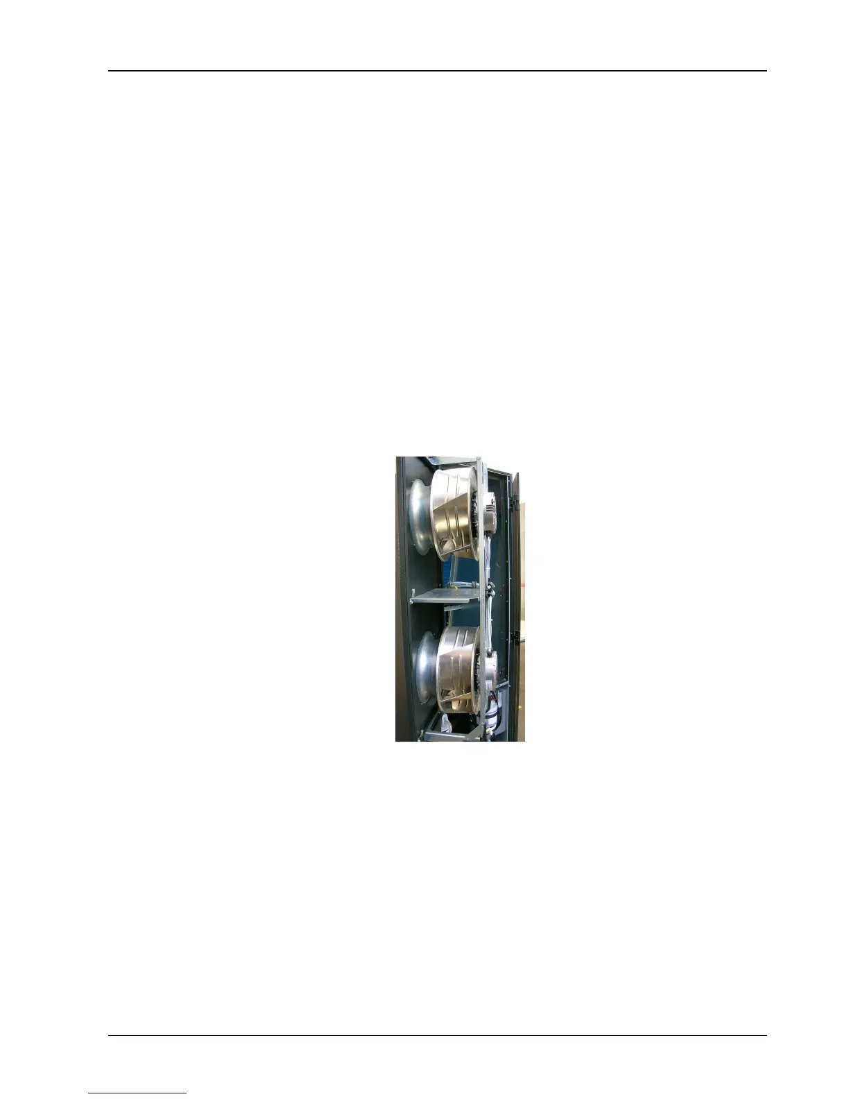
The locations of the EC fans are shown in Figure 6-3.
Figure 6-3 EC fans
The EC fans have been provided with the following protective features:
Over temperature of electronics
Over temperature of motor
Locked rotor protection
Short circuit at the motor output
With any of these failures, the motor stops (electronically-no potential separation), the status relay is released. NO
automatic restart. To reset the alarm, power supply has to be switched off for min. 20s once motor is at standstill.
Mains under-voltage detection
If mains voltage falls below 3ph/290Vac (typical value) for 5s minimum, motor will be switched off (only by electronics,
no potential separation), status relay is released.
If mains voltage returns to correct values, the motor will restart automatically.