Appendix 1 Humidair Humidifier 49
Liebert.CRV Series Air Conditioner User Manual
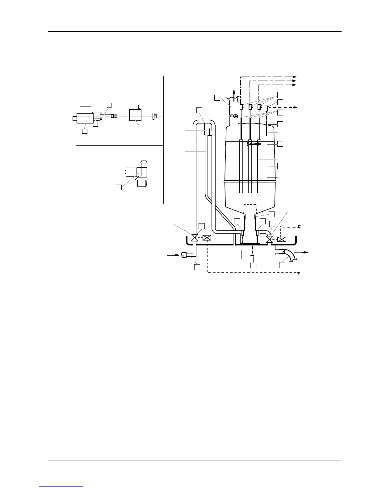
3. Humidifier Components
The components of the humidair humidifiers are shown in Figure 3.
Supply valve
P
U
L
Y
Z
C
R
V V
T
G
D
N
F
E
A
O
F
H
S
Water supply
Supply valve (F)
Filling
cup
Overflow
tube
Drain tank
Drain valve
Steam outlet
From supply
valve to interface
From humidifier
power electrodes
to electrical supply
Level electrode
Power electrodes
Steam cylinder
Water drain
outlet
From supply
valve to interface
From level sensor
to interface
Drain valve assembly (D)
Figure 3 Humidifier and its connections
4. Start-Up And Operation
4.1 Start-Up
Before using the humidifier, check the following:
Supply and drain connections.
That the cut-off tap is open.
All wiring.
Earthing.
Steam hose connection between steam cylinder and distributor.
To start the humidifier simply switch on the air conditioner, which will in turn automatically start and stop the humidifier
as required. The (adjustable) parameters which determine humidifier operation have already been factory-preset (see
iCom manual).
4.2 Operation
Water, provided it contains even a small quantity of salts in solution, is a conductor of electricity. Therefore, if the
steam cylinder is filled with water and a potential difference is applied between the electrodes, the water behaves like
an ordinary electrical resistance and becomes hot, thus creating steam. The steam production rate can be controlled