Hinet UPS User Manual
(12/01) Page 31
7.11 Remote Alarm Monitor
The RAM is realised to provide the user with a visual and audible indication of the UPS status.
It will be connected to the communications relays card of the UPS via user supplied cabling (maximum length 100m).
The RAM shall be supplied from a single phase system using an external power supply
The RAM is provided with LEDs and a horn to reflect the status of the UPS communications relays as detailed below. A
horn cancel button allows the user to mute the audible alarm for the current status. An additional LED indicates that the
RAM is operating correctly.
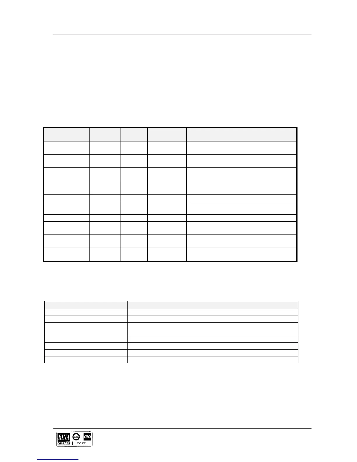
LED Name LED
Color
LED
Status
HORN
Status
CONDITIONS
UPS On Green On Off Inverter operating.
Off On Inverter not operating
On Bypass Amber On Off Load is being supplied through the bypass
Off Off Load is not being supplied through the
bypass
On Battery Amber On On Load is being supplied from battery power
Off Off Load is not being supplied from battery
power
Low Battery Red On On Shutdown imminent due to depleted battery
Off Off Shutdown is not imminent due to depleted
battery
Monitor
Power
Green On Off Power to the RAM is present and within
specification
Off Off Power to the RAM is absent or outside
specification
The Hinet terminal block need to be connected to the RAM in the following way
PIN ASSIGNMENT DESCRIPTION
2 NC Low Battery
3 COM Low Battery
4 NO UPS Run
6 COM UPS Run
7 NO Bypass ON
9 COM Bypass ON
11 NC Main Status
12 COM Main Status
Where
NC ? Normal Close Contact
NO ? Normal Open Contact
COM ? Common


 To Next Page