Do you have a question about the Life Fitness 91Xi and is the answer not in the manual?
| Brand | Life Fitness |
|---|---|
| Model | 91Xi |
| Category | Fitness Equipment |
| Language | English |
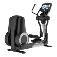
Includes operation and service manuals for the cross-trainer, providing essential user and maintenance information.
Lists touch-up paint options in various colors and quantities, along with hardware bags for repairs and maintenance.
Details the components included in the access panel assembly, featuring cables and connectors for system integration.
Components related to the drive belt, including the drive belt itself, alternator belt, and associated pulleys and bolts.
Includes the alternator, alternator flywheel, and mounting hardware like straps and nuts for power generation.
Details mounting screws, bolts, and washers used to secure the console support and related accessories.
Includes main cables, polar cables, and console caps essential for connecting the console to the machine.
Components for user convenience, such as the accessory tray kit and bullhorn grips for the console.
Includes upper and lower overlays, bezel/switch assembly, and console case for the main display unit.
Details the lower and upper console boards, which are the electronic heart of the user interface.
Contains the switch membrane for button input and the battery door for power access.
Includes the roller bearing assembly, shaft collar, and set screws that form the main roller mechanism.
Components for the crank arm, including the arm itself, extension, crank cover, and associated fasteners.
Features the poly-v crank pulley and crankshaft plate, crucial for power transmission and rotation.
Includes pillow blocks for bearing support and the magnet standoff assembly for speed sensing.
Parts for the drive linkage, including the control link with bearing assembly and the control link sleeve.
Features spherical washers, spherical end sleeves, and wave washer springs used in the linkage mechanism.
Includes left and right link covers with decals that protect the pedal linkage mechanisms.
Details the roller retainer plate and the bolts and screws used to attach the pedal covers.
Includes pillow block bearing nuts, washers, and bolts for frame stability and support.
Features the control PCB and the resistor bracket assembly with cable, critical for machine operation.
Includes clevis covers, clevis cover screws, and grommets for the front frame.
Details front cover parts (LT/RT), leg levelers, and stabilizer caps for the lower frame.
Includes wheel shaft, wheels, wheel caps, and a wheel and cap kit for smooth movement.
Contains the pedal lever, pedal clevis shaft, and associated fasteners like bolts and push-on clips.
Includes inside pedal covers (LT/RT) and tape pieces for the pedal assembly.
Features an O-ring and a beveled washer used in the pedal lever mechanism.
Includes front and rear rocker arm covers, and front and rear deadshaft covers for protection.
Details the insulator receiver tube and the polar receiver, likely for heart rate monitoring.
Features the main rocker arm component and the shaft split collar for secure mounting.
Includes hex bolts and flat washers used to assemble the rocker arm mechanism.
Includes left and right rear covers with decals, which form the outer casing for the drive system.
Details plugs and Phillips pan screws used for securing the rear drive shrouds.
Includes right and left upper arm assemblies, which are part of the user interface and movement.
Details the electrode kit, life pulse cable, and strain relief bushing for heart rate data collection.
Illustrates power control board cables and connections to the main control PCB.
Shows HR console cable, main cable, and polar cable connections to various electronic modules.
Details reed switch assembly wiring and connections to upper keypad and polar receiver.