Do you have a question about the Life Fitness 95X-ALLXX-01 and is the answer not in the manual?
| Category | Fitness Equipment |
|---|---|
| Stride Length | 20 inches |
| Resistance Levels | 26 |
| Power Requirements | AC Power Line 115 Volt, 15 Amp |
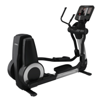
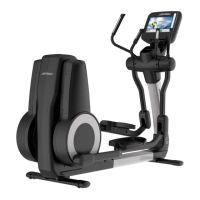
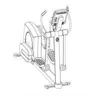
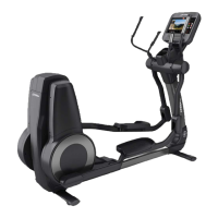
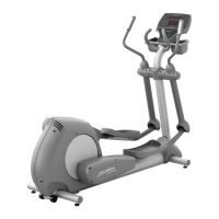
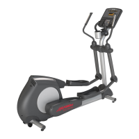
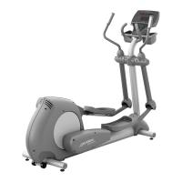
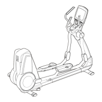
| Product Name | Life Fitness 95X Elliptical Cross-Trainer |
| Type | Elliptical |
| Heart Rate Monitoring | Lifepulse Digital Heart Rate Monitoring with DSP and Polar Telemetry |
| Maximum User Weight | 400 lbs |
| Weight Capacity | 400 lbs |
English operation manual for the cross-trainer.
Various power cords for different regions and voltage ratings.
Paint options including spray can, bottle with applicator, and pen.
Assembly for power and coax input, including bracket and connectors.
Bag containing necessary hardware for assembly or maintenance.
Description of the 7-inch Inspire LCD console for the cross-trainer.
Description of the 15-inch Engage LCD console for the cross-trainer.
Description of the Achieve LED console for the cross-trainer.
Bracket that supports the console assembly on the cross-trainer.
The upper cover section for the back of the console.
The main cover for the back of the console unit.
Complete assembly for the back cover of the console.
Tray component for holding media or devices.
Assembly for the resistance level adjustment buttons.
Protective cover for the top end of the dead shaft.
Collar component located at the front of the dead shaft.
Collar component located at the rear of the dead shaft.
End cap for the dead shaft, potentially with screw bosses.
Covers for the end caps of the dead shaft.
Kit for heart rate monitoring on the bullhorn grips.
Kit for heart rate monitoring on the handlebar grips.
Complete assembly for the left handlebar.
Complete assembly for the right handlebar.
Complete assembly for the left bullhorn grip.
Complete assembly for the right bullhorn grip.
Grommet used for securing bullhorns and handlebars.
Assembly for power and coax input, referenced from page 3.
The main vertical support column assembly.
The central shaft component of the cross-trainer's drive mechanism.
The right side cover for the swoosh-shaped body panel.
The left side cover for the swoosh-shaped body panel.
End caps for the front and rear stabilizer components.
The front stabilizing bar assembly.
Protective shrouds for the front and rear stabilizer.
Wheel component used for transporting the equipment.
Shaft for the transport wheel.
The rear stabilizing bar assembly.
The rocker arm component for the pedal mechanism.
Cover for the right front clevis joint.
Cover for the right rear clevis joint.
Cover for the left front clevis joint.
Cover for the left rear clevis joint.
Screw used for mounting clevis covers.
Complete assembly for the left pedal lever and bearings.
Bolt used for mounting the rear pedal lever.
Bearing for the rear pedal lever.
The left pedal component itself.
Hardware connecting the pedal lever to the rocker arm.
Complete assembly for the right pedal lever and bearings.
The right pedal component itself.
Top cover for the rear clevis on the pedal lever.
Bottom cover for the rear clevis on the pedal lever.
The primary cover for the main frame of the cross-trainer.
Cover for the rocking link mechanism.
The lower assembly for the left rocking link.
Screw for mounting the front rocking link.
Standard washer component used in assemblies.
Spacer component for the front rocking link assembly.
Screw for mounting the rear rocking link.
Spacer component for the rear rocking link assembly.
The lower assembly for the right rocking link.
Cover for the upper part of the rocker assembly.
External cover for the crank with an integrated decal.
Cover for the lower part of the rocker assembly.
Belt component for the rocker assembly drive system.
Assembly for the idler bracket on the right side.
Assembly for the idler bracket on the left side.
Casting for the rocker arm with integrated pulleys.
The crank arm component of the drive system.
Internal shroud assembly for the rocker mechanism.
The cover for the left side of the rear tower.
The cover for the top section of the rear tower.
The rear-most cover for the tower structure.
The cover for the right side of the rear tower.
The Poly-V belt used in the drive system.
Grommet used for cable management or mounting.
Nuts used for mounting the generator.
Washers used in various assemblies.
Assembly for the generator brake control board.
Internal cover for the crank mechanism.
The inner crank arm component, located inside the cover.
The 6-volt battery powering the unit.
Bracket for mounting the battery and GBC.
The main generator assembly for the cross-trainer.
The main drive shaft component of the upper tower.
E-ring fastener used in shaft or bore applications.
Set screws used to secure pulleys to shafts.
Bearing units mounted on pillow blocks for shaft support.
Washer with a keyway for shaft alignment.
Extension cable for power supply, with ferrite filter.
RG6 coaxial cable for signal transmission.
C-Safe cable for secure data or power connections.
Cable connecting the Generator Brake Controller to the console.
Cable connecting handlebars to the console.
Y-shaped cable for LifePulse system connections.
Cable for connecting the button assembly.
Cable connecting generator/brake to the GBC unit.
Cable connecting the battery to the system.
Cables for heart rate sensors on bullhorns.
Cables for heart rate sensors on user arms.
Flexible cable for the LifePulse system.