C4,C4P / C8, C8P Installation Manual
10 11
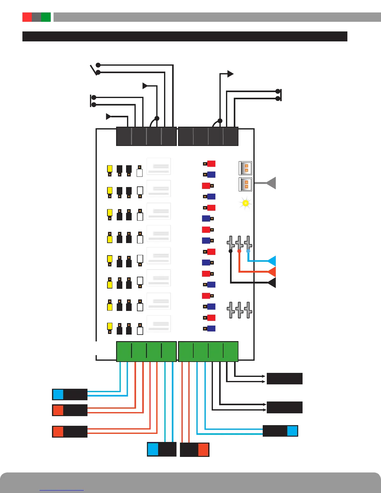
C8/C8P Application Example
NC Contact
+12/24V Voltage IN
NC Contact
NO Contact
no connection
no connection
Open Collector (Transistor) In
Open Collector (Transistor) In
NC CONTACT
OUT
NO CONTACT
OUT
DOOR
STRIKE
24V
+
–
MAG
LOCK
24V
MAG
LOCK
12V
DOOR
STRIKE
12V
+
–
+
–
+
–
DOOR
HOLDER
+
–
24V
READER
12V
+ –
BR B2 B1
BR
B1 24V
B2 12V
BR
FlexIO
B2 B1
FAULTFAULT
12
8B
8A
7B
7A
6B
6A
5B
5A
4B
4A
3B
3A
2B
2A
1B
1A
8F8D 8C 8E
1
2
INPUTS
1 2 3 4 5 6 7 8
1 2 3 4 5 6 7 8
R
R
R
R
R
R
R
R
W
W
Y
B
L
BL
BL
BL
BL
BL
BL
BL
BK BK
8D 8C 8E
Y
B
K BK
Y
W
Y
B
K BK
W
Y
B
K BK
W
W
Y
B
K BK
W
Y
B
K BK
7F
6F6D 6C 6E
5F5D 5C 5E
W
BK BK
7F4D 4C 4E
3F3D 3C 3E
2F2D 2C 2E
Y
B
K BK
1F1D 1C 1E
A B A B A B A B A B A B A B A B
A B A B A B A B A B A B A B A B
OUTPUTS
– +– +– +– +– +– +– +– +
Note: For UL Compliance, any locking device shall be configured for fail safe operation upon
occurrence of an alarm as shown with a normally closed relay contact
 Loading...
