10
Note: Use approved listed Australian Standards cable 1.0mm² TPS or larger as required by
local codes.
Terminals at back of mounting base are marked as follows:
ALARM --------------------------------- CONNECTED TO:
9V ---------------------------------- 9V (9V DC Positive Power Source)
A ------------------------------------ A (Active Side of AC Line)
SW ---------------------------------- SW (Switch wire for interconnection only)
N ---------------------------------- N (Neutral Side of AC Line)
LOOP --------------------------------- Loop dead terminal
WARNING: Connecting the Switch wire terminal to any other supply conductor may result in
damage to the alarm, failure to operate or shock hazard and void the warranty of the alarm.
• When interconnected, all Smoke Alarms will sound upon activation.
• This Smoke Alarm can only interconnect with other PSA LIFESAVER models of Smoke Alarms,Heat
alarms, CO alarms; whether of Ionisation or Photoelectric design. Interconnection with other brands
may cause damage or result in electric shock or fire risk.
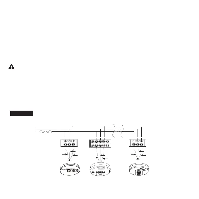
Note: For interconnection of smoke alarms to Fire Panel or Auxiliary devices, use only
LIFESAVER Isolation Relay Model LIFSAIR or LIFSAIRMB.
FIGURE 1
1 2
N
s
ss
A
N
A
N
A
24
FUSE ON
CIRCUIT
BREAKER
A
S
N
RED
WHITE
BLUE
BLUE
BLUE
WHITE
RED
A
S
N
RED
WHITE
CO ALARM
LIFESAVER
INTERCONNECT
SMOKE ALARM
LIFESAVER
INTERCONNECT
HEAT ALARM
LIFESAVER
INTERCONNECT
CONNECTION TO
A MAXIMUM OF 24 DEVICES
LOOP
N
SW
A
9V
LOW
BATTERY
POWER
FLASHING
=ALARM
1Flash
=SERVICE
Model: NLCO
EN50291-1: 2010
License No
.
KM98848