5
CAUTION: Disconnect power supply before beginning installation.
Remove the old thermostat from the wall taking note of the wire colors on the
back of the mounting kit provided. Thread the thermostat cable through the hole
on the back of the Lightstat TME. Mount the Lightstat TME securely to the wall
using the hardware provided. The Lightstat TME should be leveled for cosmetic
reasons.
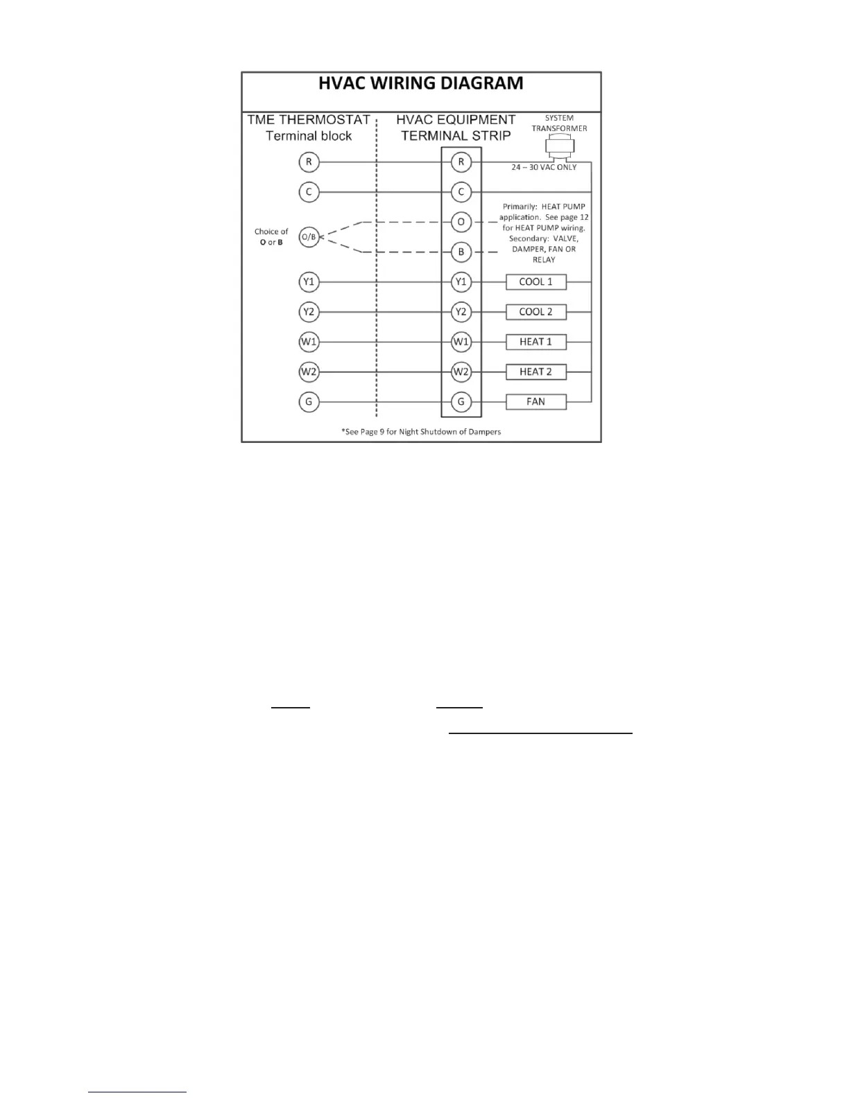
Connecting the Outputs
R - Hot Wire; one side of control (24-30VAC) transformer. If two hot wires are
present (as with RC and RH) determine if they come from separate transformers.
The Lightstat TME must be installed on a single transformer system.
C - Common or Neutral side of transformer. This must be connected.
O/B - This output may be active with either a call for Heat (B) or a call for Cool
(O) but not both. It is typically used for a heat pump reversing valve.
Y1 - First Stage of Cooling. There is a 1º(F) differential between any two stages
of Heating or Cooling.
Y2 - Second stage of Cooling.
W1 - First stage of Heating.
W2 - Second stage of Heat or Auxiliary heat with heat pumps.
G - Air Circulating fan. The Lightstat TME will control the fan during the cooling
cycle. Fan operation during the Heating cycle depends on the setting of switch
#4 on page 15. The Lightstat TME allows for either constant ON operation of the
fan or AUTO operation. The fan reverts to AUTO in Setback.