Introduction
The DVI-HDCP-TPS-TX95 and DVI-HDCP-TPS-RX95 are DVI 1.0 and HDMI 1.4 compatible
long distance extenders. The units offer bi-directional RS-232, Infra-Red (IR), and Ethernet
pass-through all on the same CAT5e...CAT7* cable that carries the uncompressed HDMI
video and audio signal.
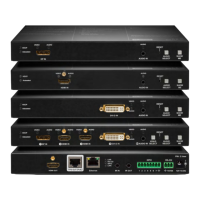
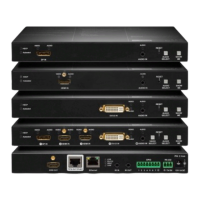
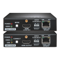
Typical standalone application - the transmitter and the receiver
Installation of a transmitter and a receiver
1. Power off all devices. (Installing with powered devices may harm them.)
2. Check the RS-232 switches (2) on the TX and RX; they must be in Normal position.
3. Set the desired TPS link mode with the TPS link mode switch (3) on the front of the units.
4. Set the desired TX remote power** mode with the jumpers on the right side of the TX.
5. Connect a CATx* cable to the TPS OUTPUT (7) on the TX.
6. Connect the video source and the desired accessory devices to the TX.
7. Set the desired RX remote power** mode with the jumpers on the right side of the RX.
8. Connect the other end of the CATx* cable to the TPS INPUT on the RX.
9. Connect the video sink and the desired RS-232, IR and Ethernet devices to the RX.
10. Supply the extenders with 12V 2A DC. If the remote power is enabled on both sides only one
local adaptor can be used. Else both units must be powered by local adaptors.
11. Supply the other connected units.
* CAT7 SFTP cable is always recommended.
** Never connect any third party device to the extender with remote powering.
Warning! The TPS remote powering must be used only with 95 series TPS extenders and
MX-TPS matrix boards. Using it with other devices may damage both units.
Warning! Do not connect any device to the TPS connector unless you are sure they are
compatible. Connecting incompatible devices with similar connectors may cause harm to
the devices.
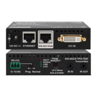
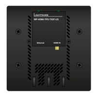
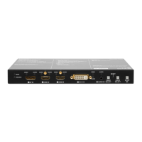
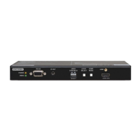
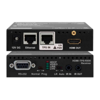
Front and rear view
Info: Transmitter and receiver have the same construction and connectors.
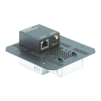
Remote power options
The TPS extenders can be powered remotely by its extender pair or a TPS matrix board. This
feature can be enabled or disabled with jumper settings. Switch off the extenders. On the
right side of the enclosure a small section (in the blue box) can be removed. Loose the
screws and remove the plate. Jumpers are under it. To enable the remote power function
place the jumper block onto all the pinheads. To disable it place the jumper block onto the
upper line pinheads only. In case of enabled remote power on both extenders the local
adaptor can be placed at any side. To better understand the remote power options see the
Figure 1 on the page 4.