Dimensions Maximum Extension Distances
Below values are valid when the receiver is powered by a local adaptor; distances may
decrease depending on the powering mode (local or remote) and cable quality.
Resolution
Pixel
clock rate
Cable lengths
(Auto / Long reach TPS mode)
CAT5e
AWG24
CAT7
AWG26
CAT7
AWG23
1024x768@60Hz 65 MHz 100 m / 130 m* 90 m / 120 m* 120 m / 170 m*
1280x720p@60Hz 73.8 MHz 100 m / 130 m* 90 m / 120 m* 120 m / 170 m*
1920x1080p@60Hz (24bpp) 148.5 MHz 100 m / 130 m* 90 m / 120 m* 120 m / 170 m*
1920x1200@60Hz 152.9 MHz 100 m / NA 90 m / NA 120 m / NA
1600x1200@60Hz 162 MHz 100 m / NA 90 m / NA 120 m / NA
1920x1080@60Hz (36bpp) 222.75 MHz 70 m / NA 70 m / NA 120 m / NA
3840x2160@30Hz UHD ** 297 MHz 70 m / NA 70 m / NA 100 m / NA
4096x2160@30Hz 4K ** 297 MHz 70 m / NA 70 m / NA 100 m / NA
* Long reach TPS mode supports pixel clock frequencies up to 148.5 MHz.
CAT7 SFTP AWG23 cable is always recommended.
Receiver and Front plate
model
Dimensions (mm)
Recommended outlet box type
for mounting
a b c
1
c
2
WP-HDMI-TPS-RX97-EU 80 150 24,5 33,4
European two gang panel
Part no.: 77190-D3
WP-HDMI-TPS-RX97-UK 80 140 24,5 33,4
Appleby galvanised steel
knockout boxes 2g 47mm
WP-HDMI-TPS-RX97-US 114.3 115.9 24,5 33,4 Carlon B225R
WP-HDMI-TPS-RX97-FP-8AT 104,5 111,5 24,5 33,4 Legrand 8AT
FP-HDMI-TPS-RX97-GB3 44.8 134.5 24,5 33,4
OBO Bettermann: UT4; Part no.:
7408727
Cover plate: OBO Bettermann
UT4 P3; Part no.: 7408 76 1
Legrand 89610
Bidirectional Pass-through Data Lines
The direction of the video extension is xed
from TX towards RX but the pass-through data
lines are bidirectional*. It means the RS-232,
IR, Ethernet source and sink devices can be
connected either to the TX or to the RX and the
signal is transmitted to the other extender.
* In fact IR transmission is uni-directional but
the extender has two IR channels with different
directions.
RS-232
Third party devices with standard RS-232 port are supported as the extenders work in „pass-
through” mode. TX and RX provide 3-pole Phoenix connector. The RS-232 options – the baud
rate and the parity bits are set on the third party devices and it can be anything. The extenders
support any kind of serial settings.
Please nd the RS-232 device type in its user guide; the extenders work as DCE devices.
Ethernet
The Ethernet port on the RX or on TX can be connected to a LAN hub, switch or router with a
LAN cable. The other side behaves as an Ethernet uplink port. The extenders support 10/100
Mbps data transfer rate.
The Ethernet port has auto crossover function. It is able to recognize
and handle both cable types: patch and cross TP cables.
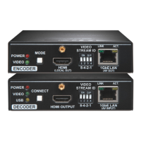
TPS Link Modes
The TPS working mode between the transmitter and the receiver parties is determined by
the mode set in them. Both parties inuence on the setting which determines the nal TPS
transmission mode. The following TPS modes are dened:
Long reach (LR): Longer CATx cable length, less bandwidth (limited resolution). The
LPPF mode is not available in LR TPS link mode.
HDBaseT
TM
(HDBT): more bandwidth (higher resolutions), shorter CATx cable length. If
no video present, the units change to LPPF mode automatically.
Low Power Partial Functionality (LPPF): Only Ethernet, RS-232 and IR are extended.
Toggling between TPS link modes
The toggle switch on the extenders can
be used to toggle between the LR and
Auto TPS modes. If both units have Auto
state and there is valid video signal on
the transmitter the common mode will
be HDBT. If the video signal disappears
devices go into LPPF mode.
TPS mode between an extender and a
port of a matrix board
If an extender and a TPS matrix board are paired the board forces the extender to use the
settings of the matrix. The extender’s TPS mode switch has no effect.
Always use the Auto mode with third-party devices.
The negotiated
TPS working mode
Selected mode (RX)
LR Auto
Selected
mode
(TX)
LR LR LR
Auto LR HDBT
SERIAL
ETHERNET
INFRA #1
INFRA #2
TX
RXTX
Specications
General
Compliance ................................................................................................... CE, UKCA
Electrical safety .................................................................................. EN 62368-1:2014
EMC (emission) ............................................................................. IEC/EN 55032:2015
EMC (immunity) ............................................................................. IEC/EN 55035:2017
RoHS .....................................................................................................EN 63000:2018
Warranty ............................................................................................................. 3 years
Operating temperature ...................................................0° to +50°C (+32° to +122°F)
Cooling ................................................................................................. by a cooling fan
Weight ......................................................................................... approx. 370g (0.82 lb)
Power
Power supply .......................... external power adaptor / PoE (IEEE 802.3af) via TPS
Power adaptor ......................... Input 100-240 V AC 50/60 Hz, Output 48V DC, 0.5 A
Power consumption ................................................................... 6.5W (typ) / 8W (max)
DC power connector ..............................................................2-pole Phoenix connector
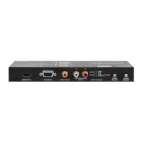
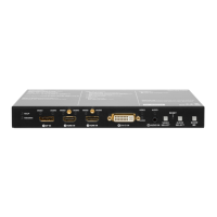
Connectors
RX input ........................................................................................RJ45 (TPS interface)
RX output ..............................................................................................HDMI connector
Ethernet ................................................................................................................. RJ45
IR input, output ................................................................ 3.5 mm (1.8”) jack connector
Serial port ................................................................................................3-pole Phoenix
Digital video signal
Supported signals ........................................................................... DVI 1.0, HDMI 1.4
Signal standard ................ DVI and HDMI standard which supports embedded audio
Supported resolutions .............. up to 4K / UHD (30Hz RGB 4:4:4, 60Hz YCbCr 4:2:0)
............................................................................................1920x1080@120 Hz, 24 bit
3D support ............................................................................................................... yes
HDCP compliant ...................................................................................................... yes
Control over CEC ................................................................yes, only over HDMI signal
EDID support .............................................................................................. transparent
Equalization .................................................................................... adaptive, automatic
Infrared (IR)
One emitter and one detector is enough for remote controlling one IR sink device. If there
is an IR sink device to be controlled next to the TX and the other one is next to the RX, two
emitter-detector pairs are needed. The IR emitter and the detector have standard 3.5 mm TRS
(jack) connectors. The emitter’s plug has two poles (mono) and the detector’s plug has three
poles (stereo).
The emitter and detector pair is not supplied with the product, it can be ordered from
Lightware separately.
Types of IR Connectors (1/8” TS / TRS )
Detector – 3-pole-TRS Emitter – 2-pole-TS
1 Tip Signal (active low) 1 Tip +5V
2 Ring GND 2 Ring
Signal (active low)
3 Sleeve +5V 3 Sleeve
Assembly Guide of the Bare Extender and the Front Plate
¢
Always apply ESD-protection during the assembling. Electric
discharge may harm the electric parts of the device.
¢
Please unplug all cables from the device before performing the
steps described below.
The following assembly steps can be applied for the following extender models and front plates:
Name Type Description
WP-HDMI-TPS-RX97 bare Extender WP-HDMI-TPS-RX97 receiver device
WP-HDMI-TPS EU plate Accessory Front plate suitable for Double EU wall box
WP-HDMI-TPS UK plate Accessory Front plate suitable for Double UK wall box
WP-HDMI-TPS US plate Accessory Front plate suitable for Double US wall box
WP-HDMI-TPS FP-8AT plate Accessory Front plate suitable for Legrand 8AT oor box
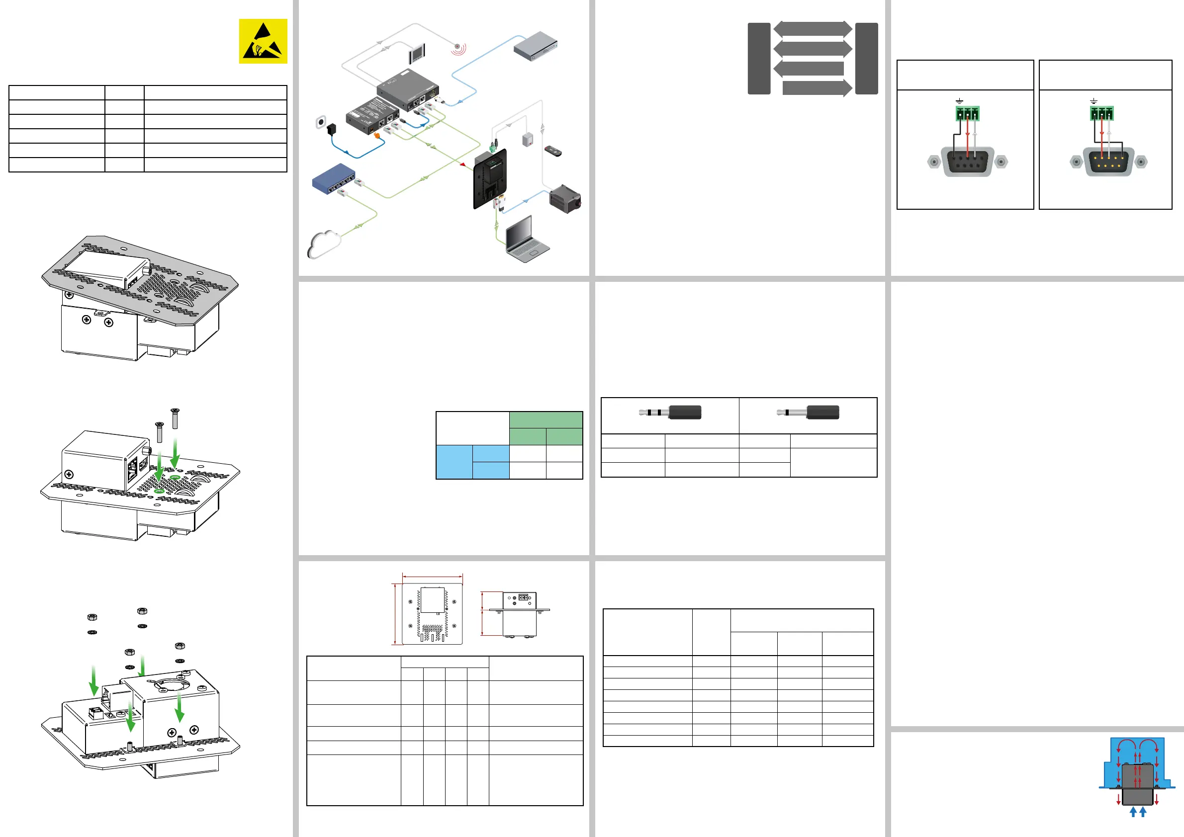
Assembly Steps
1. Place the front plate to the bare extender device like it is shown on the gure below. Place
the cutout of the front plate under the HDMI ange screw.
2. Suit the front plate like it shall be lying down the device.
3. Place and screw the provided two pieces M3x12 PZ at head black screws into the
screw holes shown in the gure below. It requires a PZ1 screwdriver.
4. Turn the device upside down.
5. Place provided four pieces M3 bright zinc plated toothed washers to the screws. After
it is done, place and screw four pieces M3 metric nuts onto the built-in screws with a
5,5mm socket wrench key.
Find more details about the assembly steps of the extender and the mounting
options to the wall plates / oor plates in our Mounting Options and Accessories for
WP/FP-HDMI-TPS-97 series Extenders assembly guide on the website www.lightware.com.
Typical Application
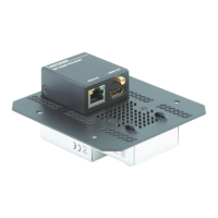
Ventilation
¢
To ensure the correct ventilation and avoid overheating
mount the extender into an industrial standard switch/outlet
box. Let enough free space in front of the appliance and
keep the ventilation holes free.
The picture on the right side shows the direction of the airow.
c
1
c
2
a
b
IR cable
Serial
cable
IR emitter
HDMI
Blu-Ray or DVD Player
LAN
Ethernet switch
HD Projector
Touch panel
Sn:
Made in EU, Hungary
RoHS
Ethernet 10/100
Bidirectional IR
Bidirectional RS-232
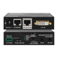
TTPPSS LLoonngg DDiissttaannccee TTrraannssmmiitttteerr
HDMI, 3D, 4K supported
For best performance use AWG23 CAT6 or CAT7 SFTP cable
PIN: 2mm
12V 1A DC
H
D
M
I
--T
P
S
--T
X
9
7
Device can be remote powered over TPS link with PoE
(IEEE 802.3af)
TPS OUT
PoE
( )
TPS-PI-1P1
LAN
HDMI-
TPS-TX97
48V DC
Power
adaptor
LAN
IR detector
HDMI
IR cable
Serial cable
ETHE RNET
WP-HDMI-TPS-RX97
T
ypical: 0.5A
Max: 1.25A
- +
Max:2.5A
mm2 :NIP
IR OUT
IR IN
LINK
TX RX
LIVE
SIGNAL
WP-HDMI-TPS-RX97-US
HDMI OUTEthernet
CATx
TPS connection
CATx up to 170m
Power
send
Wiring Guide for RS-232 Data Transmission
WP/FP-HDMI-TPS-RX97 series are built with 3-pole Phoenix connector. See the below
examples of connecting to a DCE (Data Circuit-terminating Equipment) or a DTE (Data
Terminal Equipment) type device:
Lightware device and a DCE
D-SUB 9 - Phoenix
Lightware device and a DTE
D-SUB 9 - Phoenix
1
6
9
5
2: TX data transmit
3: RX data receive
1
6
9
5
2: TX data receive
3: RX data transmit
For more information about the cable wiring see the user’s manual of the device or
Cable Wiring Guide on our website www.lightware.com/support/guides-and-white-papers.
OUT
OUT
 Loading...