Do you have a question about the Lincoln Electric EAGLE 10,000 and is the answer not in the manual?
| Brand | Lincoln Electric |
|---|---|
| Model | EAGLE 10, 000 |
| Category | Welding System |
| Language | English |
State-specific warnings regarding engine exhaust.
Safety precautions for engine-powered equipment.
Warnings about EMF fields and pacemakers.
Critical warnings about avoiding electrical shock.
Precautions against arc ray exposure.
Safety measures for welding fumes and gases.
Precautions to prevent fires from welding sparks.
Safety guidelines for compressed gas cylinders.
Detailed technical data for the welder and engine.
General safety guidelines to follow before installation and operation.
Procedures for proper grounding of the machine.
Information on spark arrester requirements.
Guidelines for safely towing the equipment.
Safety considerations for mounting the welder on a vehicle.
Lubrication system capacity and oil type.
Instructions and precautions for connecting the battery.
Recommendations for selecting welding cable sizes.
Maximum allowable engine operating angle.
Safe procedures and equipment for lifting the machine.
Specific advice for operating at high altitudes.
Instructions for relocating the exhaust muffler.
Proper placement for airflow and exhaust ventilation.
Guidance for connecting wire feeders.
Specific connection procedure for LN-25 feeder.
Procedure for connecting the TIG module.
Extra safety advice for operating the welder.
General guidelines for operating the welder.
Details on providing auxiliary AC power.
Specifications for the dual voltage outlet.
Guidelines for using 120V outlets.
Information on starting motors using auxiliary power.
Permitted simultaneous welding and power loads.
Guidelines for using the welder as standby power.
Essential safety measures before operating the machine.
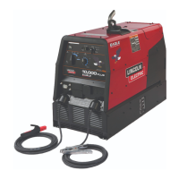
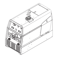
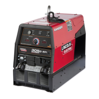
Overview of the welder's features and construction.
Explanation of the welder's controls and their functions.
Operation of the engine start, idle, and stop switch.
Selection of amperage ranges for welding processes.
Fine adjustment of welding current.
Estimated fuel usage for different operating modes.
Procedures for starting and stopping the engine safely.
Initial engine break-in procedures and oil change recommendations.
Guidelines for various welding processes.
Procedures for wire feed welding.
Using the welder for arc gouging.
Table summarizing welding process parameters.
List of optional accessories available for field installation.
Recommended equipment for different welding types.
Information on plasma cutting accessories.
Critical safety warnings for performing maintenance.
Daily checks and tasks for machine upkeep.
Step-by-step guide for changing engine oil.
Specific oil capacities for the engine.
Maintenance for air cleaner, switches, and cleaning.
Information on engine adjustments like governor settings.
Inspection and maintenance of slip rings and brushes.
Notes on fastener types used.
Safety and procedures for battery maintenance.
List of common engine maintenance parts.
Explanation of the basic components and their roles.
How rotor field feedback affects output and auxiliary power generation.
Function of weld winding, reactor, and range switch in current control.
AC to DC conversion and output filtering process.
Instructions on how to use the troubleshooting section.
Steps for diagnosing and replacing PC boards.
Procedure to test DC voltage applied to the rotor.
Test to check for shorted or grounded rotor windings.
Procedure to test AC voltages from stator windings.
Test to determine if rectifier bridge diodes are faulty.
Test to verify the functionality of the charging system.
Procedure to check and adjust engine RPM.
Steps for accessing and replacing generator brushes.
Procedure for removing and installing the main circuit board.
Steps for removing and replacing the output rectifier bridge.
Procedures for removing and replacing the engine or rotor assembly.
Guidelines for retesting the machine after repairs.
Electrical wiring schematic for machine code 11096.
Electrical wiring schematic for machine code 11397.
Overall machine schematic for code 11096.
Overall machine schematic for code 11397.
Schematic diagram for the Idler/Field Control PC Board.