Do you have a question about the Lincoln Electric Flextec 500 and is the answer not in the manual?
Emphasizes user responsibility for safe operation and reading the manual.
Advice on managing welding fumes and ensuring proper ventilation.
Guidance on wearing protective equipment and general safety practices.
Precautions for welding materials that may release toxic fumes or gases.
Specific warnings required by California law regarding diesel exhaust and welding fumes.
General hazards associated with arc welding, including advice for pacemaker wearers.
Safety guidelines for operating and maintaining engine-powered equipment.
Information and precautions regarding Electric and Magnetic Fields (EMF) during welding.
Detailed instructions on preventing electric shock while operating welding equipment.
Guidelines for protecting eyes and skin from arc rays using shields and protective clothing.
Information on the dangers of welding fumes and gases and necessary precautions.
Measures to prevent fires and explosions caused by welding sparks and hot materials.
Critical safety guidelines for handling and storing compressed gas cylinders to prevent explosions.
Safety requirements for installation and grounding of electrically powered equipment.
Lists the welding processes the Flextec™ 500 is designed for, including materials and electrodes.
Outlines any limitations or restrictions on the processes the Flextec™ 500 can perform.
Lists standard equipment packages available for the Flextec™ 500.
Details various optional kits and accessories like work lead packages and carts.
Details on analog and ArcLink wire feeders that are compatible with the Flextec™ 500.
Options specific to Stick and TIG welding, including accessory kits and torches.
Information on power source input voltage, current, and power factor ratings.
Guidelines for selecting appropriate input wire and fuse sizes based on voltage.
Details the rated output in amps, volts, and duty cycle for various welding processes.
Provides physical dimensions and operating/storage temperature ranges for the unit.
Lists the conformity marks and markets for which the Flextec™ 500 is approved.
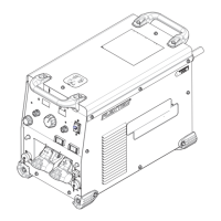
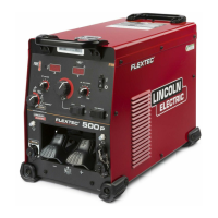
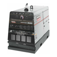
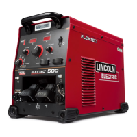
Describes the innovative features and benefits of the Flextec™ 500's design.
Instructions for making the essential input power and grounding connections for the machine.
Details the critical grounding requirements for the Flextec™ 500 frame.
Recommendations for fuse types, wire sizes, and circuit breakers for the input power circuit.
How to set the correct input voltage for the machine and potential error messages.
Guidelines for placing the welder to ensure adequate cooling and ventilation.
Procedures for safely lifting the machine and its stacking limitations.
Advice on environmental limitations and avoiding interference with radio-controlled equipment.
Details the pinout and wiring for connecting analog wire feeders.
Details the pinout and wiring for connecting ArcLink wire feeders.
General recommendations for routing, connecting, and coiling weld cables to optimize performance.
Charts detailing recommended cable sizes based on amperage, duty cycle, and cable length.
Recommendations for using Lincoln control cables and best practices for cable placement.
Overview of how voltage sensing works and its importance for arc performance.
Details the requirements for voltage sense leads based on weld process and polarity.
Definitions and illustrations of graphic symbols found on the machine and in the manual.
Explains the duty cycle capabilities of the Flextec™ 500 at different amperage ratings.
Guides on making a weld and lists the 5 selectable welding modes.
Details controls like Output Control Dial, Volt/Amperage Meters, and toggle switches.
Explains the function of switches like Wire Feeder Polarity and indicator lights like Thermal and VRD.
Details operation in SMAW mode, including controls and displays.
Details specific control functions like Output Control Local/Remote and Output Control Dial for SMAW.
Details operation in GTAW mode, including controls and displays.
Explains control functions such as Output Control Local/Remote and Output Control Dial for GTAW mode.
Details operation in CV-GAS mode, covering controls like Output Control and displays.
Describes control functions like Output Control Local/Remote and Output Control Dial for CV-GAS mode.
Details operation in CV-Innershield mode, including controls and displays.
Explains control functions like Output Control Local/Remote and Output Control Dial for CV-Innershield mode.
Details operation in ArcLink mode, noting that most Flextec controls are disabled.
Explains that most Flextec controls are disabled in ArcLink mode, with control handled by the wire feeder.
Details various optional kits and accessories like work lead packages and carts.
Information on fume extracting systems and flowmeter regulators.
Lists compatible analog and ArcLink wire feeders.
Options specific to Stick and TIG welding, including accessory kits and torches.
Explains the thermal protection system and how thermostats manage overheating.
Instructions for performing a visual inspection of the machine's components.
Outlines routine cleaning and inspection tasks to be performed every six months.
Explains the three-step process for locating problems, identifying causes, and recommending actions.
Details specific error codes and the corresponding corrective actions to resolve issues.
Steps to diagnose and resolve issues when the machine fails to produce weld output.
Guidance on addressing the thermal symbol being lit, checking fan operation and output ratings.
Troubleshooting steps for wire feeder not working, checking connections and power.
Detailed wiring diagram illustrating internal electrical connections of the Flextec™ 500.
Diagram showing how to connect the Flextec™ 500 to an Across-the-Arc wire feeder.
Shows the connection setup for the Flextec™ 500 when using LN10 or DH10 wire feeders.
Diagram showing how to connect the Flextec™ 500 to the FlexFeed 74 HT wire feeder.
Diagram showing how to connect the Flextec™ 500 to the LN25 Pro Dual Power wire feeder.
Diagram showing how to connect the Flextec™ 500 to the PF84 wire feeder.
Detailed dimensional drawing of the Flextec™ 500 with specific measurements.
An indexed list of major sub-assemblies comprising the Flextec 500.
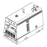
Visual depiction of the Case Front Assembly.
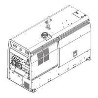
Visual depiction of the Divider Panel Assembly.
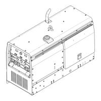
Visual depiction of the Base & Center Assembly.
Visual depiction of the Case Back Assembly.
Visual depiction of the Wraparound Assembly.
Lists all parts included in the Case Back Assembly, with quantities.
Lists all parts included in the Wraparound Assembly, with quantities.
| Efficiency | 85% |
|---|---|
| Power Factor | 0.93 |
| Protection Class | IP23 |
| Output Range | 5-500 Amps |
| Input Voltage | 208/230/460/575 V |
| Phase | 3-Phase |
| Processes | MIG, Stick, TIG |
| Rated Output | 500 A at 32 VDC |
| Duty Cycle | 60% at 500 Amps |