

K
Kenneth JohnsonJul 30, 2025
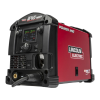
Why is my Lincoln Electric POWER MIG 210 MP arc unstable and has poor starting?
- JjlewisJul 30, 2025
An unstable arc and poor starting in your Lincoln Electric Welding System can stem from several factors: * Incorrect input voltage. * Improper electrode polarity. * A worn, damaged, or improperly sized gun tip. * Incorrect gas or flow rate. * Loose or faulty work cable connections. * Damage to the gun. * Improper drive roll orientation and alignment. * An improperly sized liner. If you've checked these areas and the problem continues, contact your local Lincoln Authorized Field Service Facility.