Do you have a question about the Lincoln Electric POWER MIG 255 SVM144-B and is the answer not in the manual?
| Brand | Lincoln Electric |
|---|---|
| Model | POWER MIG 255 SVM144-B |
| Category | Welding System |
| Language | English |
Warnings regarding chemicals known to cause cancer, birth defects, or reproductive harm.
Key safety guidelines for operation, electrical hazards, fumes, and arc exposure.
Essential safety measures to follow before and during equipment installation.
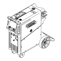
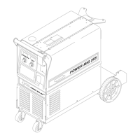
Instructions for safely uncrating the machine and selecting an appropriate location.
Detailed guidance on connecting input power, grounding, and wiring diagrams.
How to set and understand electrode polarity for optimal welding.
Steps for properly installing the welding gun and associated cables.
Critical safety warnings related to electric shock, fumes, sparks, and arc rays during operation.
Overview of the machine's features, welding capabilities, and limitations.
Explanation of the function of each control on the machine's panel.
Procedures for changing drive rolls and loading wire reels, spools, or coils.
Step-by-step instructions for starting the welder and making a weld.
Details on available drive roll kits for different wire sizes and types.
Available gun and cable assemblies for enhanced performance.
Instructions for installing the optional timer kit for added functionality.
Information regarding the adapter for using spool guns with the welder.
Safety guidelines to follow before performing any maintenance tasks.
Recommended daily and periodic cleaning and inspection tasks.
Procedures for cleaning drive rolls, guide tubes, and cable liners.
Guidelines for maintaining gun tubes and nozzles, including tip replacement.
Procedures for removing, replacing, and trimming the gun liner.
Explanation of how input voltage is processed by the main transformer.
How AC output is rectified and controlled using SCRs and feedback signals.
The process of filtering DC output to achieve a constant voltage.
How the control board manages the wire drive motor speed using feedback.
Details on the machine's built-in protective systems against overheating and overloads.
Explanation of how Silicon Controlled Rectifiers (SCRs) function in controlling output.
Instructions on how to effectively use the troubleshooting guide to diagnose issues.
Guidelines for troubleshooting and replacing PC boards, including static precautions.
Guides for output, function, wire feeding, and welding problems.
Tests for transformer, rectifier, SCRs, and wire drive motor.
Visual representations of normal and abnormal waveforms for diagnostic purposes.
Steps for replacing PC boards, wire drive, SCRs, capacitors, transformer, and fan.
Guidelines and specifications for retesting the machine after repairs.
Complete wiring diagram for machines with Code 10563.
Complete wiring diagram for machines with Code 10583.
Complete wiring diagram for machines with Code 10986.
Complete wiring diagram for machines with Code 10990.
Schematic and assembly diagrams for the control PC board.
Schematic and assembly diagrams for the display PC board.
Schematic and assembly diagrams for the snubber PC board.