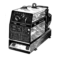
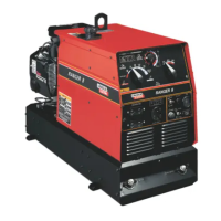
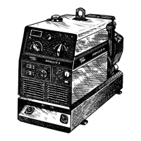
EasyManua.ls Logo

Lincoln Electric RANGER 9 User Manual

Lincoln Electric RANGER 9
41 pages
To Next Page IconTo Next Page
Page #1 background imageLoading...
Page #1 background image
OPERATOR’S MANUAL
For use with machines having Code Number 10378, 10379, 10539, 10540 and 10550
RANGER
TM
9
Multi-Process Gasoline Engine Driven Welder and Power Generator
IM511-D
OCTOBER, 2000
Safety Depends on You
Lincoln arc welding and cutting
equipment is designed and built
with safety in mind. However, your
overall safety can be increased by
proper installation ... and thought-
ful operation on your part. DO
NOT INSTALL, OPERATE OR
REPAIR THIS EQUIPMENT
WITHOUT READING THIS
MANUAL AND THE SAFETY
PRECAUTIONS CONTAINED
THROUGHOUT. And, most
importantly, think before you act
and be careful.
R
• Sales and Service through Subsidiaries and Distributors Worldwide •
Cleveland, Ohio 44117-1199 U.S.A. TEL: 216.481.8100 FAX: 216.486.1751 WEB SITE: www.lincolnelectric.com
• World's Leader in Welding and Cutting Products •
Date of Purchase:
Serial Number:
Code Number:
Model:
Where Purchased:
Copyright © 2000 Lincoln Global Inc.

Questions and Answers:

Lincoln Electric RANGER 9 Specifications

General IconGeneral
Max Output9, 000 Watts
Output Range30 - 300 Amps
Rated Output250A DC at 25V, 100% Duty Cycle
Fuel TypeGasoline
DC OutputYes
TypeEngine-Driven Welding Generator
Open Circuit Voltage80 Volts
Engine ModelKohler CH440
Engine Power14 HP
Fuel Tank Capacity5 Gallons
ProcessesStick, TIG
Generator Output9, 000 Watts
Auxiliary Power120/240 Volts, 60 Hz
Welding ProcessesStick, TIG

Summary

Safety Precautions: Hazards and Warnings

California Proposition 65

State warnings regarding cancer, birth defects, and reproductive harm from engine exhaust.

Arc Welding Hazards

Advisories on protecting oneself and others from serious injury or death during arc welding.

Electric and Magnetic Field (EMF) Risks

Information on potential health effects and precautions regarding EMF fields from welding.

Electrical and Environmental Safety

Electric Shock Prevention

Steps to prevent electric shock, including insulation, dry gloves, and avoiding simultaneous contact.

Arc Ray Protection

Using shields, proper lenses, and flame-resistant clothing to protect from arc rays.

Fumes and Gases Safety

Avoiding breathing fumes, using ventilation, and precautions for toxic fumes.

Fire, Explosion, and Equipment Safety

Welding Sparks and Fire Hazards

Removing fire hazards, covering openings, and keeping extinguishers ready.

Compressed Gas Cylinder Safety

Precautions for handling compressed gas cylinders, securing them, and location.

Electrical Equipment Safety

Safety measures for electrically powered equipment, including grounding and disconnect switches.

General Description and Capabilities

Product Overview

Description of the Ranger 9 as a twin cylinder gasoline engine driven welder and generator.

Supported Processes and Auxiliary Power

Lists supported welding processes and details the auxiliary power generator.

Technical Specifications

Machine and Engine Data

Lists machine model, output, dimensions, weight, and engine specifications.

Optional Features and Accessories

Undercarriages, Covers, and Kits

Describes optional undercarriages, covers, spark arresters, and accessory kits.

Electrical and Control Options

Lists GFCI receptacle kits, TIG modules, and remote controls as optional features.

Recommended Equipment for Welding

Stick, TIG, and Wire Feeder Gear

Lists recommended equipment for stick, TIG, and wire feed welding processes.

Installation Instructions

Grounding and Spark Arresters

Guidelines for grounding the welder and installing an optional spark arrester.

Undercarriage Mounting Considerations

Factors for mounting the welder to an undercarriage, ensuring stability and safety.

Pre-Operation Service and Checks

Oil, Fuel, and Battery Setup

Instructions for checking oil, fueling, and connecting the battery before operation.

Welding Cables and Location

Guidance on connecting output cables and selecting a proper location for the welder.

Operating Procedures and Guidelines

Engine Operation Angles and Altitude

Recommended operating angles and high altitude operation advice for the engine.

Muffler Relocation

Instructions for changing the exhaust side of the muffler for noise level adjustment.

Wire Feeder Connections

LN-25 Feeder Connections

Specific instructions for connecting LN-25 wire feeders with remote control modules.

Wire Feeder and Control Module Connections

LN-7, LN-8, and LN-742 Feeder Connections

Procedures for connecting LN-7, LN-8, and LN-742 wire feeders to the Ranger 9.

Spool Gun, TIG, and Remote Control Setup

Instructions for connecting spool guns, TIG modules, and remote output controls.

Operating Instructions and Controls

Welder Output and Fuel Consumption

Details welder output capabilities and approximate fuel consumption for different operating modes.

Welder Control Functions

Explains the function of the engine start, polarity, and range switches.

Control Switches and Engine Starting

Idler and Terminal Switch Operations

Describes the operation of the idler and welding terminals switches for different modes.

Engine Starting and Shutdown Procedures

Step-by-step instructions for starting the engine and basic shutdown guidelines.

Welding Processes and Settings

Stick and TIG Welding

Instructions for stick and TIG welding, including current ranges and TIG module use.

Wire Feed Welding

Details on wire feed welding, including recommended electrodes and wire types.

Welding Process Summary

Process Setting Configuration

A table summarizing settings for stick, TIG, and wire feed welding processes.

Auxiliary Power Management

115V and 115/230V Receptacle Usage

Information on 115V and dual voltage receptacles, current limits, and automatic idle features.

Auxiliary Power and Standby Connections

Permissible Power Loads

Table showing permissible auxiliary current and wattage for different output settings.

Standby Power Installation Guidance

Guidance for installing the Ranger 9 as a standby power unit for permanent installation.

Premises Wiring Connection Diagram

Wiring Schematic for Site Connection

Schematic illustrating the connection of the Ranger 9 to premises wiring, including breakers and plugs.

Maintenance Procedures

Maintenance Safety and Engine Adjustments

Warnings for maintenance, engine speed limits, and qualified personnel requirements.

Routine Maintenance Schedule

Outlines daily and periodic maintenance tasks for the engine and welder, including oil changes.

Battery and Parts Information

Battery Charging and Safety

Safety warnings regarding battery explosion and acid hazards during charging or replacement.

Common Maintenance Parts

List of common maintenance parts for Onan and Kohler engines.

Troubleshooting: Engine Issues

Engine Cranking, Starting, Power, and Charging

Common causes and solutions for engine not cranking, starting, power loss, or charging problems.

Troubleshooting: Idler System

Engine Idle Speed Control Problems

Addresses issues with the engine not idling down or not accelerating correctly.

Troubleshooting: Output System

No Output or Control Malfunctions

Diagnosing no welder/power output, control switch, potentiometer, and wiring issues.

Wire Feeder Connection Troubleshooting

Diagnosing problems with wire feeder connections to the welder.

Troubleshooting: Output System (Cont.)

Contactor Operation Issues

Troubleshooting contactor not pulling in or not dropping out during various operations.

Wiring Diagram: Ranger 9 (Onan)

Codes 10378 & 10539

Wiring diagram for Onan models, specific to codes 10378 and 10539.

Wiring Diagram: Ranger 9 Onan (CSA)

Codes 10379 & 10540

Wiring diagram for Onan CSA models, specific to codes 10379 and 10540.

Wiring Diagram: Ranger 9 Kohler (CSA)

Code 10550

Wiring diagram for Kohler CSA models, specific to code 10550.

Wire Feeder Connection Diagrams

LN-25 Across Arc and LN-7/K867 Connections

Diagrams for connecting LN-25 and LN-7/K867 wire feeders to the Ranger 9.

Wire Feeder Connection Diagrams (Continued)

LN-7 and K867 Adapter Connections

Diagrams illustrating LN-7 and K867 adapter connections to the Ranger 9.

Wire Feeder Connection Diagrams (More)

LN-8 and LN-742 Connections

Diagrams showing LN-8 and LN-742 wire feeder connections to the Ranger 9.

Wire Feeder Module and Amptrol Adapter Diagrams

LN-25 Module and K915-1 Amptrol Adapter

Diagrams for LN-25 module and K915-1 Amptrol adapter connections.

Spool Gun Connection Diagram

K691-10/K488/K487 Spool Gun System

Diagram for connecting spool gun systems like K691-10, K488, and K487.

Dimension Print - Ranger 9

Ranger 9 Dimensional Data

Technical drawings showing the physical dimensions and mounting points of the Ranger 9.

Related product manuals