Do you have a question about the Lincoln Electric SP-100 and is the answer not in the manual?
Details potential dangers and necessary precautions related to electric shock during welding operations.
Explains the risks associated with arc rays and the required protective measures.
Covers the dangers of welding fumes and gases, emphasizing ventilation and health precautions.
Addresses the hazards of welding sparks causing fires or explosions and preventative measures.
Highlights the risks associated with compressed gas cylinders and safe handling practices.
Provides safety guidelines for powered equipment, including EMF and engine-specific precautions.
Details input voltage, current, output ratings, cable sizes, and physical dimensions for the SP-100.
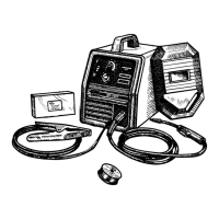
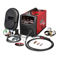
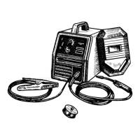
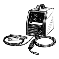
Lists safety instructions and guides on unpacking and identifying SP-100 parts.
Explains choosing a location and connecting output components like the work clamp and cable.
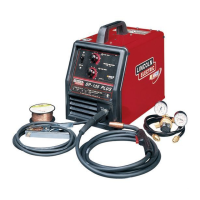
Details gun installation, gas connection, and input power connections with safety notes.
Outlines electrical code compliance and provides recommendations for using extension cords.
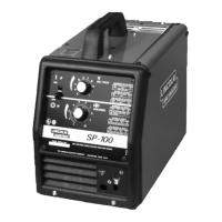
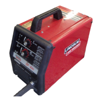
Provides an overview of the SP-100, its features, and controls like Power, Voltage, and Wire Speed.
Identifies suitable welding processes (GMAW, Innershield) and outlines the machine's capabilities and limitations.
Details the process for threading welding wire and adjusting the wire spool friction brake.
Guides on setting up shielding gas and performing a weld, including polarity and gas checks.
Covers gun cleaning, Innershield welding, and the machine's overload protection systems.
Details available regulator kits for shielding gases and kits for Innershield welding.
Lists options for drive rolls and common replacement parts for the SP-100 welder.
Highlights safety precautions and covers routine checks required before and after use.
Provides instructions for replacing the gun's contact tip and changing the drive roll for different wire sizes.
Details procedures for replacing the gun cable liner and accessing internal gun handle parts.
Illustrates and identifies the locations of various subassemblies and components within the SP-100.
Explains how input voltage, fan motor, and the main transformer function in the SP-100.
Details how output voltage is controlled, rectified, and regulated using SCRs and feedback mechanisms.
Describes the functional interaction between the trigger, gas solenoid, and wire drive motor.
Explains the fundamental working principles of Silicon Controlled Rectifiers (SCRs) in controlling welding output.
Details the thermal protection system that prevents overheating by controlling output and fan operation.
Provides a step-by-step guide on how to effectively use the troubleshooting chart to diagnose and resolve issues.
Offers specific steps and precautions for troubleshooting and replacing printed circuit boards.
Lists common output problems, potential causes, and recommended actions for diagnosis and repair.
Covers problems related to wire feed, gas flow, unstable arcs, and poor starting.
Explains waveform analysis for diagnosing faults and procedures for removing fan and wire drive components.
Specifies retesting procedures required after mechanical or electrical component repair or replacement.
Presents the electrical wiring diagram for SP-100 models with code numbers 9794 and higher.
Shows the electrical wiring diagram for SP-100 models with code numbers below 9794.
Diagram illustrating component placement on the G1842 control PC board.
Diagram showing the layout of components on the G2314 control PC board.
Provides the overall machine schematic for SP-100 models with code numbers 9794 and higher.
Presents the overall machine schematic for SP-100 models with code numbers below 9794.
| Input Voltage | 120 V |
|---|---|
| Input Phase | Single Phase |
| Input Frequency | 60 Hz |
| Output Amperage Range | 30 - 100 A |
| Welding Process | MIG (GMAW) |
| Wire Size Range | .030 - .035 in |
| Wire Feed Speed Range | 50-700 IPM |