Do you have a question about the Lincoln Electric SPEEDTEC 405SP and is the answer not in the manual?
Details input voltage, EMC class, and frequency for the welding machines.
Specifies output voltage and current for various welding processes at different duty cycles.
Defines the operational current ranges for different welding modes.
Provides guidance on suitable input cable and fuse types for the equipment.
Details efficiency and idle power consumption for models.
Instructions for minimizing electromagnetic disturbances during operation and installation.
Covers electric shock, power, EMF, optical radiation, fumes, and arc rays hazards.
Details risks of sparks, hot materials, gas cylinders, and moving parts.
Guidelines for placing the machine in a suitable environment.
Explains duty cycle and the effects of overheating on the machine.
Instructions on connecting the welding machine to the power supply.
Guidance on making output connections for welding.
Explains the power switch and system status light.
Covers thermal overload indicator and replaceable panel options.
Details negative/positive output sockets and control receptacle for connectivity.
Details specific fuses and sockets for cooler and gas connections.
Instructions for connecting the user interface, welding cables, and water cooler.
Daily checks for lead condition, welding gun, and cooling fan.
Includes routine checks plus cleaning dust and tightening weld terminals.
| Brand | Lincoln Electric |
|---|---|
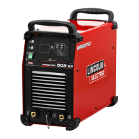
| Model | SPEEDTEC 405SP |
| Category | Welding System |
| Language | English |