EasyManua.ls Logo

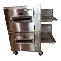
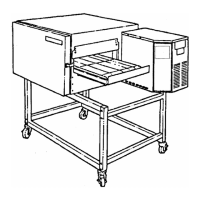
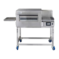
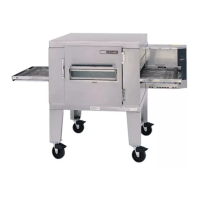
Lincoln 1600 Service Manual

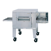
Lincoln 1600
68 pages
To Next Page IconTo Next Page
Page #1 background imageLoading...
Page #1 background image
1600SvcMan REV: 12/13/05
SERVICE MANUAL
(DOMESTIC & INTERNATIONAL)
IMPINGER CONVEYOR OVENS
LOW PROFILE - 1600 SERIES
Lincoln Foodservice Products, Inc.
1111 North Hadley Road
P.O. Box 1229
Fort Wayne, Indiana 46801-1229
Phone: (800) 374-3004 • Fax: (260) 436-0735
Technical Service Hot Line
(800) 678-9511
www.lincolnfp.com
Question and Answer IconNeed help?

Do you have a question about the Lincoln 1600 and is the answer not in the manual?

Lincoln 1600 Specifications

General IconGeneral
BrandLincoln
Model1600
CategoryOven
LanguageEnglish

Summary

Sequence of Operations 1600 / 1601 / 1652

Sequence of Operations 1622 / 1623

Sequence of Operations / 1628 / 1629

Sequence of Operations / 1646, 1647, 1650, 1651

Schematic / 1600, 1601, 1652

Schematic / 1622, 1623

Schematic / 1628, 1629

Schematic / 1646, 1647, 1650, 1651

Troubleshooting Gas Ovens Model 1600, 1601, 1652

Troubleshooting / 1622, 1623, 1628, 1629 Electric Ovens

Troubleshooting / 1646, 1647, 1650, 1651 Gas Ovens

Removal, Installation & Adjustments Model Series 1600

Sail Switch, Cooling Fan - Replacement

Steps for replacing the cooling fan sail switch.

Burner Control - Honeywell - Replacement

Steps for replacing the burner control unit.

Burner Blower Motor - Replacement

Procedure to replace the burner blower motor.

Hot Surface Igniter - Replacement

Instructions for replacing the hot surface igniter.

Conveyor Control Potentiometer and Timer Replacement

Conveyor Control Board Replacement and Dip Switch Settings

Procedures for replacing/calibrating the control board and setting dip switches.

Time Calibration and Fuseholder Replacement

Gas Valve Replacement and Adjustments

Burner Alarm Replacement

Steps for replacing the burner alarm.

Component Replacement and Calibration Procedures

Main Orifice, Temperature Potentiometer, and On-Off Switch Replacements

Procedures for replacing main orifice, temp pot, and switches.

Dual Time/Temperature Display Replacement and Calibration

Instructions for replacing and calibrating the dual time/temp display.

Time Calibration Procedures

Time/Temp Simulator and Dip Switch Settings

Procedure for Use of Time/Temp. Simulator

Guide for using the time/temp simulator.

Transformer and Control Replacements

Transformer-Time/Temperature Display Replacement

Steps for replacing the time/temp display transformer.

Burner Control Transformer Replacement

Procedure for replacing the burner control transformer.

Conveyor Control Transformer Replacement

Steps for replacing the conveyor control transformer.

Capacitor, Main Fan Motor Replacement

Procedure for replacing the main fan motor capacitor.

Temperature Control and Thermostat Replacements

Mercury Contactor Replacement

Steps for replacing the mercury contactor.

Electronic Temperature Control Replacement

Procedure for replacing the electronic temperature control.

High Limit Thermostat Replacement

Steps for replacing the high limit thermostat.

Motor and Thermocouple Replacements

Heating Element Replacement

Procedure for replacing the heating element.

Cooling Fan Motor Replacement

Steps for replacing the cooling fan motor.

Main Fan Motor Replacement

Procedure for replacing the main fan motor.

Thermocouple (Type J) Replacement

Steps for replacing the thermocouple.

Sensor Replacement Procedures

Thermistor, 10K Ohm Replacement

Procedure for replacing the 10K ohm thermistor.

Hall Effect Sensor Replacement

Steps for replacing the hall effect sensor.

Conveyor and Bearing Replacement

Conveyor Drive Motor Replacement

Procedure for replacing the conveyor drive motor.

Bearing, Conveyor Replacement

Steps for replacing conveyor bearings.

Gas System Components Replacement and Adjustment

Air Pressure Switch Replacement and Adjustment

Procedure for replacing and adjusting the air pressure switch.

Burner Alarm Replacement

Steps for replacing the burner alarm.

Ignition System Component Replacement

Spark Generator Replacement

Steps for replacing the spark generator.

Ignition Control Replacement

Procedure for replacing the ignition control.

Igniter Sensor Assembly Replacement

Steps for replacing the igniter sensor assembly.

Parts / General - 1600 Series

Blow Up / General – 1600 Series

Exploded view of general parts for the 1600 series.

Parts / Control Box, Right- 1600 - 1601 - 1652

Blow Up / Control Box Right – 1600, 1601, 1652

Exploded view of right control box parts.

Parts / Control Box, Left - 1600 - 1601 - 1652

Blow Up / Control Box Left – 1600, 1601, 1652

Exploded view of left control box parts.

Parts / Control Box, Right –1622,1623,1628,1629

Blow Up / Control Box Right – 1622,1623,1628,1629

Exploded view of right control box parts for 1622-1629 models.

Parts / Control Box, Left 1622,1623,1628,1629

Blow Up / Control Box Left – 1622, 1623, 1628, 1629

Exploded view of left control box parts for 1622-1629 models.

Parts / Control Box Right – 1646, 1647, 1650, 1651

Blow Up / Control Box Right – 1646,1647,1650,1651

Exploded view of right control box parts for 1646-1651 models.

Parts / Control Box Left – 1646, 1647, 1650, 1651

Blow Up / Control Box Left – 1646,1647,1650,1651

Exploded view of left control box parts for 1646-1651 models.

Parts / Back - 1600 Series

Blow Up / Back – 1600 Series

Exploded view of back parts for the 1600 series.

Parts / Conveyor - 1600 Series

Blow Up / Conveyor – 1600 Series

Exploded view of conveyor parts for the 1600 series.

Related product manuals