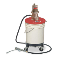
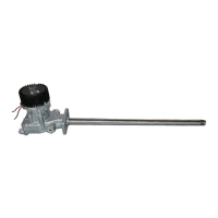
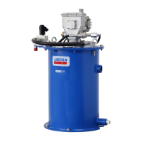
This document describes air-operated lubrication units, specifically Models 4417, 4459, 4489, and bare pump assemblies 274216 & 274217, designed for dispensing automotive greases directly from containers to the lubrication point. These units are suitable for various applications, including industrial settings, and are designed for dispensing lubricants from drums or p25-50# pails.
Function Description
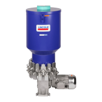
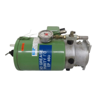
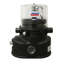
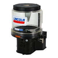
The primary function of these units is to pump and dispense lubricants, typically grease, from a container to a desired lubrication point. They operate using compressed air, which powers a pump mechanism to draw lubricant from the drum or pail and deliver it through a hose and control valve. The air motor is designed to provide consistent pressure for efficient lubricant delivery. The units are capable of handling various types of grease, including those used in automotive and industrial applications. The control valve allows the operator to regulate the flow of lubricant, ensuring precise application. Some models are equipped with a follower plate that helps to keep the lubricant clean and ensures that the pump draws all the material from the container, minimizing waste. The system is designed to maintain a steady flow of lubricant, even with higher viscosity greases, by utilizing appropriate air pressure and pump ratios.
Usage Features
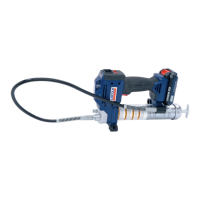
These lubrication units are designed for ease of use and portability, making them suitable for various work environments. The drum and pail models come with a dolly or cart, allowing for easy movement around a workshop or facility. The control valve, often equipped with a Z-swivel, provides flexibility and reduces strain during operation. The units are designed to be connected to a compressed air supply, and proper air pressure regulation is crucial for optimal performance. The control valve features a non-spring guard end that is always connected to the control valve, ensuring a secure connection.
For initial pump priming, the unit requires the air inlet to be connected, and the air pressure should be set between 20-40 PSIG. The control valve should be opened to allow air to escape, and the pump will begin to operate slowly, drawing lubricant. Once the pump begins to operate smoothly and lubricant flows freely from the pump tube, the air pressure can be increased to the desired operating pressure for normal use.
Basic pump operation involves adjusting the air pressure to achieve the desired lubricant flow. Too much air pressure can cause the pump to operate very rapidly, potentially damaging equipment. When the pump is not in operation, the air supply to the pump should be disconnected, and the air pressure on the control valve and grease hose should be relieved. This ensures safety and prevents accidental discharge.
The units are designed to be robust and durable, capable of withstanding the demands of daily use in a workshop environment. The hose and control valve are integral parts of the system, providing the means to deliver lubricant accurately. The follower plate, when included, helps to prevent air pockets and ensures efficient material evacuation from the container.
Maintenance Features
Regular maintenance is essential to ensure the longevity and optimal performance of these lubrication units. The manual emphasizes the importance of following safety instructions and proper maintenance procedures.
Troubleshooting:
- Pump does not operate: This could be due to a clogged muffler or an empty lubricant reservoir. Corrective actions include cleaning or replacing the muffler, or refilling the lubricant container.
- Pump operates but lubricant is not delivered: Possible causes include air pockets in the lubricant, dirt/checks in the control valve, worn or damaged plunger, or water in the air supply. Solutions involve refilling the reservoir, disassembling and cleaning/replacing control valve items, replacing the plunger, or installing an air filter/lubricator.
- Pump operates but lubricant is expelled from exhaust muffler: This indicates a damaged upper U-cup seal or piston rod. Repairing or replacing these components is necessary.
- Air is leaking from exhaust when pump is stalled: This suggests worn or damaged air piston(s) or piston seals, or a damaged air cylinder. Replacing damaged components is required.
- Pump is stalled: This could be due to broken return springs, which need to be replaced.
Control Valve & Swivel Repair:
The control valve and swivel are not serviceable items and should be replaced if damaged or leaking. Disassembly is not recommended as it could lead to improper function.
High Humidity Operation:
In high humidity conditions, moisture can mix with lubricant, forming an emulsion that can hinder pump operation. To prevent this, a moisture control unit should be installed in the air supply line. If the muffler is blocked with ice, it should be removed and cleaned. For severe conditions, a water-resistant #1 grease should be used, and the muffler should be removed for proper operation.
Pump Repair:
For pump repair, it is recommended to use genuine Lincoln service parts. The manual provides a detailed list of service parts and their corresponding item numbers. For complex repairs, it is advisable to contact an authorized Lincoln Service Dealer or Lincoln Technical Services Department.
Regular checks for leaks, especially at connections and seals, are crucial. Any leaks should be addressed promptly to prevent lubricant waste and maintain system efficiency. The air supply should be clean and dry to prevent contamination of the lubricant and damage to the pump's internal components.