Do you have a question about the Lincoln QUICKLUB 203 and is the answer not in the manual?
Highlights critical safety steps before performing maintenance or repairs.
Covers safety equipment, heat sources, and the use of original Lincoln spare parts.
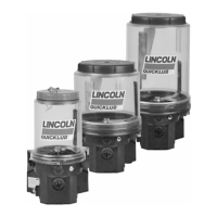
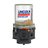
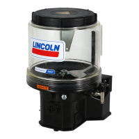
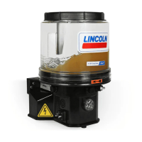
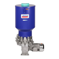
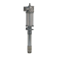
Details the components and capabilities of the compact multiline pump.
Explains the operation of pump elements with fixed lubricant output and lists available designs.
Introduces the adjustable pump element and its operating principle.
Step-by-step guide on how to adjust the lubricant output using the adjusting spindle.
Details how pause time determines lubrication frequency and its adjustability.
Explains how lubricating time depends on lubricant requirements and is adjustable.
Guides on how to set pause and lubricating times by removing the pump housing cover.
Details setting pause time using the blue rotary switch and jumper positions.
Details setting lubricating time using the red rotary switch and jumper positions.
Instructions for conducting an operational test and triggering additional lubrication cycles.
Explains fault signals indicated by the right-side LED and rotary switch positions.
Provides guidance on how to remedy identified faults on the control PCB.
Instructions for filling the reservoir with clean lubricant and important notes on cleanliness.
Guidance on using original spare parts and returning pumps for warranty or major repairs.
Step-by-step instructions for removing and installing pump elements.
Critical safety warnings and precautions for electrical connections.
Methods for connecting a pressure gauge to check the relief valve's opening pressure.
Refers to the 'Operational Test' section for functional checks of control PCBs.
Diagnoses causes for the pump motor not running and provides remedies.
Identifies reasons for lubricant delivery failure and suggests operator or service remedies.
Provides detailed electrical input/output data, protection, and monitoring features.
| Model | QUICKLUB 203 |
|---|---|
| Category | Water Pump |
| Manufacturer | Lincoln |
| Power Source | Electric |
| Type | Lubrication Pump |