Subject to modifications
Owner Manual
Operating Instructions
2.2A-10001-G07
Page 6 of 36
LINCOLN GmbH • Postfach 1263 • D-69183 Walldorf • Tel +49 (6227) 33-0 • Fax +49 (6227) 33-259
Installation
Tube Fittings, Screw-Type
4239a99
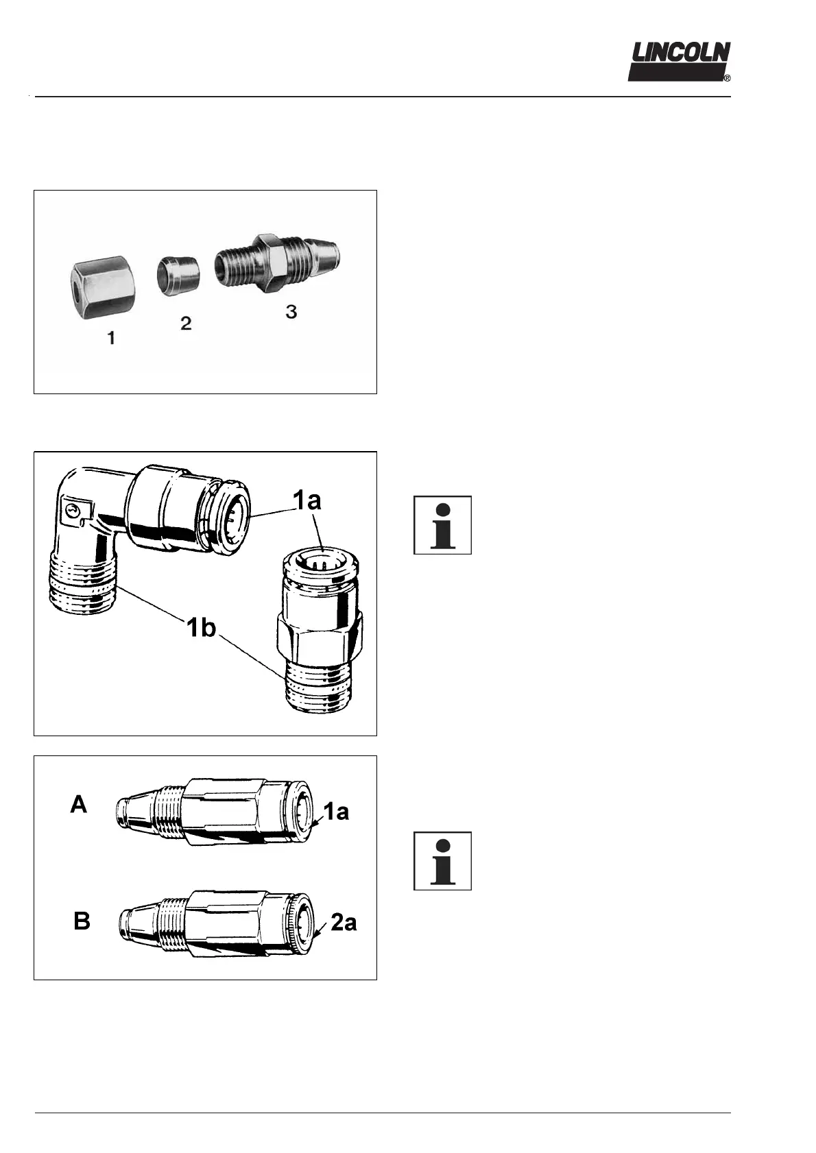
Fig. 1 Single parts of the check valve
Main- and secondary Metering devices
Inlet tube fittings, straight and 90°
As inlet fitting use only tube fittings R1/8” thread.
Check valves
Install one complete check valve in each outlet borehole
which will be used.
Install one closure plug in each outlet borehole which will be
not used. Exception: outlet bore hole 1 and/or 2 on SSV 6 to
SSV 22. In both boreholes check valves have to be installed.
Check valves for tube dia. 4 mm and 6 mm are available.
1 - coupling nut
2 - ferrule
3 - valve body with seal and
clamp ring
Tube Fittings, Push-in Type
1008a98
Fig. 2 Inlet fittings
1009a98
Fig. 3 The different types of check valve
Metering Devices
Inlet tube fittings, straight and 90 °
6001a02
IMPORTANT
For the inlet fittings use only tube fittings
with reinforced collet 1a (Fig. 2) and
sealing ring 1b at the thread.
1a - Collet
1b - Sealing ring
Check valves
Main metering device
Use check valves type A, Fig.3 with reinforced collet 1a
and smooth flange (Part no. 226-14091-4).
Secondary metering device
Use check valves type B, Fig. 3 with standard collet 2a
and knurled flange (Part no. 226-14091-2).
6001a02
NOTE
On construction machines or agricultural
machines use high-pressure hoses. In
such cases the check valves of the secon-
dary metering devices must have a rein-
forced collet and smooth flange.
A - Check valve with reinforced collet
B - Check valve with knurled collet
1a - reinforced collet
2a - knurled collet



 To Next Page