Local console connections: Video
The LINDY KVM IP uses DVI/I video ports that support both digital and analogue
video monitor connections. The LINDY KVM IP automatically converts between
the two connection styles to ensure independence between the locally
connected video monitor, the remote user’s video monitor and the graphics
capabilities of the host computer(s).
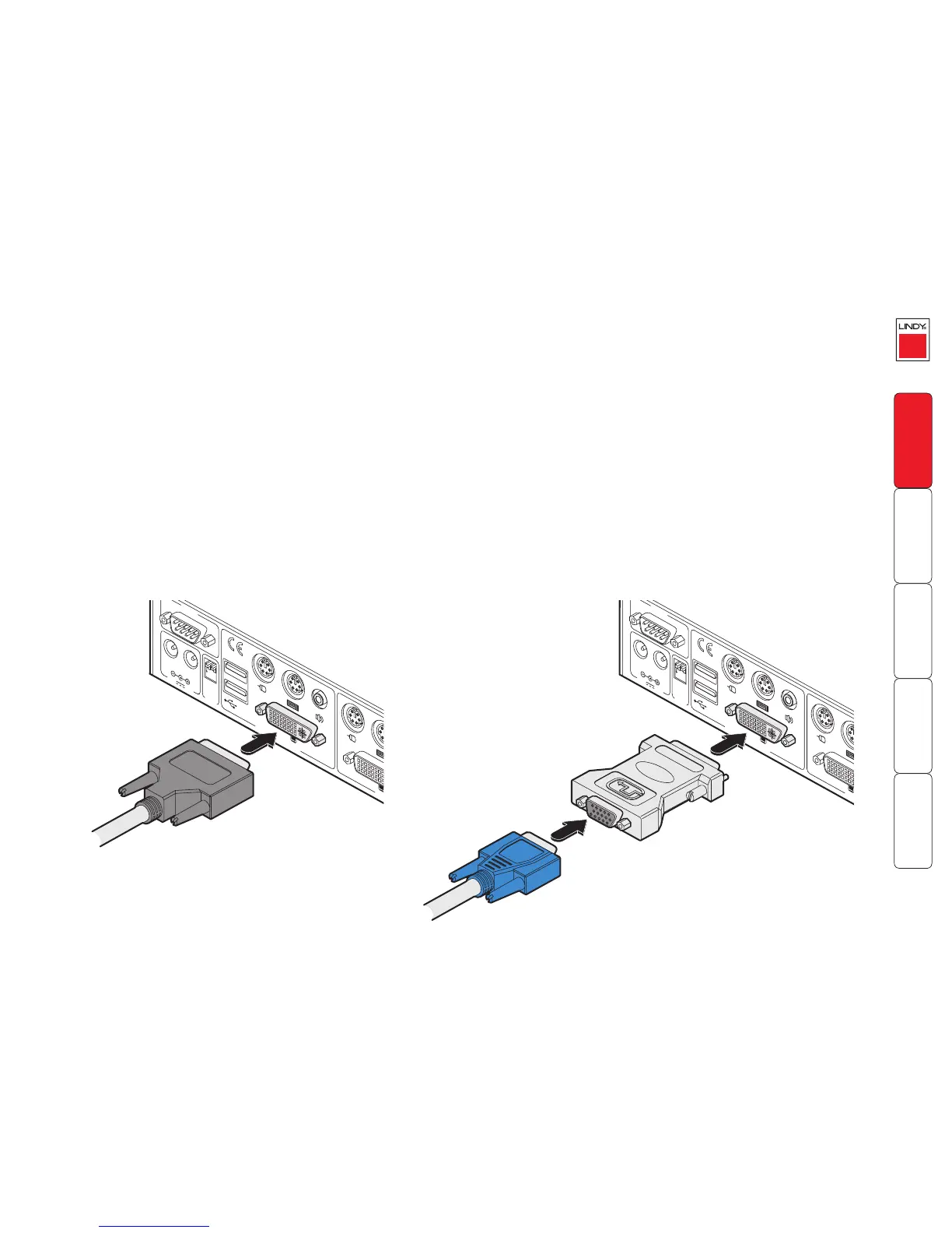
To connnect a local video monitor
1 Wherever possible, ensure that power is disconnected from the LINDY KVM
IP.
2 As appropriate, attach a suitable digital or analogue video monitor to the
DVI/I socket on the rear panel of the LINDY KVM IP unit:
• Digital Connect the digital video monitor cable to the port labelled DVI
VGA within the KVMA CONSOLE section of the rear panel.
• Analogue Connect a converter module to the port labelled DVI
VGA within the KVMA CONSOLE section of the rear panel. Connect
the analogue video monitor cable to the converter module. In both
cases, ensure that the securing screws are used to maintain reliable
connections.