Modem/ISDN port
The LINDY KVM IP provides a serial port specifically for you to connect either a
modem or ISDN terminal adapter. This can be used as a primary, secondary or
backup access port for remote systems, as best suits your overall configuration.
IMPORTANT: When the LINDY KVM IP is accessible from the public Internet or dial
up connection, you must ensure that sufficient security measures are employed.
To connect a modem or ISDN port
1 Wherever possible, ensure that power is disconnected from the LINDY KVM
IP and the modem or ISDN adapter.
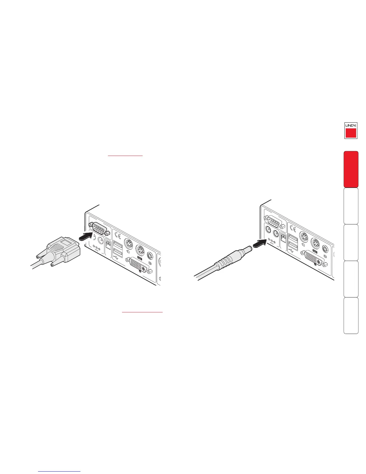
2 Connect a suitable serial modem (non-crossover) cable to the serial port on
the modem/ISDN adapter.
3 Connect the other end of the serial cable to the port labelled MODEM at the
rear of the LINDY KVM IP.
Note: The default serial port speed is 115200 and a standard Hayes-compatible
auto-answer string is sent during startup. The default startup string is
‘ATZHS0=1’. Both the serial port speed and startup string settings can easily be
altered during the local or remote configuration - see Initial configuration for
more details. The other serial settings are fixed at: No parity, 8 bit word and 1
stop bit.
Power supply connection
The LINDY KVM IP is supplied with a single power supply and an appropriate
country-specific IEC power lead. However, it has two power input sockets to
allow a second power supply to connected as a fail-safe. The LINDY KVM IP can
operate easily from a single power input. However, when two power supplies
are connected, the power load is shared between them. There is no on/off
switch so operation begins as soon as a power supply is connected.
To connect the power supply
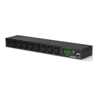
1 Connect the low voltage output lead from the power supply unit to either
power socket on the rear panel of the LINDY KVM IP.
2 If required, connect the low voltage output lead from a second suitable
power supply to the other power socket on the rear panel of the LINDY
KVM IP.
3 Connect the IEC connector of the supplied country-specific power lead to
the socket of the power supply. Repeat for the second power supply, if used.
4 Connect the power lead(s) to a nearby main supply socket.
Note: The correct operation of one or both connected power supplies are
confirmed during power-up by the A and B indicators on the front panel as
power is applied.