7
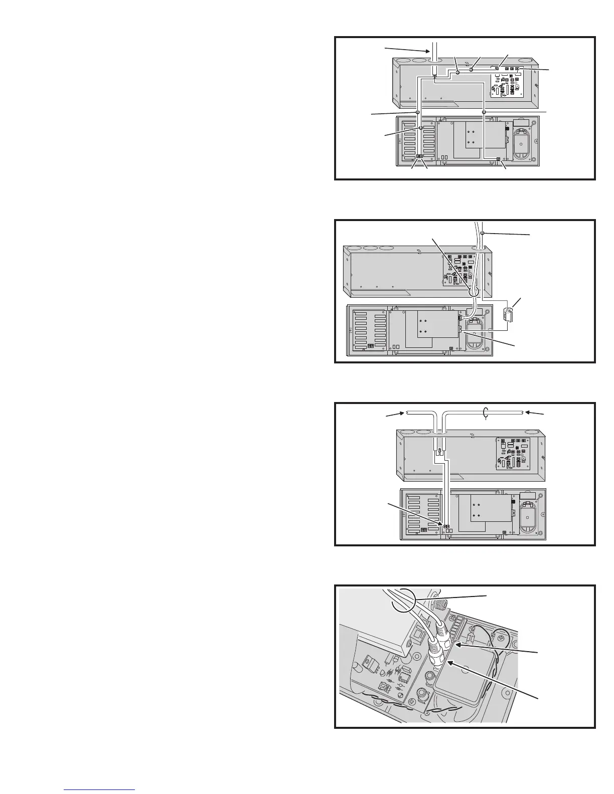
Door Station Connection to Master Station
The Door Station connects to the two screw terminals
between the quick connector sockets. If the Door Station
has a bell button, it connects to the optional chime module.
1. Connect the BLACK wire from the Door Station to the screw terminal
labeled DOOR BLACK on the DMC1 Master Station.
2. Connect the RED wire from the Door Station to the screw terminal
labeled DOOR RED on the DMC1 Master Station.
3. Connect the ORANGE wire from the Door Station to the screw
terminal labeled COMMON on the chime module (if chime is used)
4. Connect the YELLOW wire from the Door Station to one of the NOTE
screw terminals on the chime module (if chime is used). DO NOT
CONNECT THE YELLOW WIRE TO MORE THAN ONE NOTE
TERMINAL.
5. Connect the shield wire from the Door Station to the terminal
labeled SHIELDS on the DMC1 Master Station. NOTE: THE SHIELD
WIRE MUST BE INSULATED TO PREVENT IT FROM TOUCHING
ADJACENT COMPONENTS. SLIDE ON SOME INSULATION FROM
A STRIPPED WIRE.
Antenna Connections
The DMC1 contains an AM/FM tuner. Radio reception
requires installation of an AM wire lead antenna, and an FM
dipole antenna. The antennas should have been installed
during the rough-in and require connecting to the DMC1
Master Station.
1. The AM antenna is the single ORANGE wire lead that has the ferrite
fi lter on it. Connect the ORANGE wire to the AM ANTENNA terminal
on the side of the tuner module in the DMC1 Master Station. The
GROUND terminal remains un-connected.
2. The FM antenna is the coax wire with the Type “F” connector. Connect
the coax wire to the FM ANTENNA connector on the side of the tuner
module in the DMC1 Master Station.
Door Release Connection
The DMC1 Master Station can be wired to a Model DRW
electric door strike. The door release relay has normally open
contacts that are rated at 2 Amps @ 24 Volts AC/DC. The relay
can be activated from the DMC1 Master Station or remote scan
Room Stations (Model DMC1RS) by pressing the volume up
and volume down buttons together for four seconds. The relay
will deactivate when the buttons are released.
1. Identify the two cables labeled “Door Release”.
2. Use a wire nut to connect one wire from the transformer cable to one
wire from the door strike.
3. Connect the remaining wires from each cable to the terminals marked
DOOR RELEASE on the DMC1 Master Station.
External Music Source Connection
Audio from an optional wall plate connects to the DMC1
auxiliary audio inputs.
Follow these steps if using the audio input wall plate
1. Identify the two RCA cables labeled “AUX INPUT”.
2. Insert the left audio cable RCA plug into the AUX L jack on the DMC1
Master Station.
3. Insert the right audio cable RCA plug into the AUX R jack on the
DMC1 Master Station.
MS4DCXSC
CABLE TO
DOOR STATION
BLACK
WIRE
RED
WIRE
DOOR BLACK DOOR RED
SHIELD
WIRE
NOTE: SLIDE
INSULATION
ON SHIELD
WIRE TO
PREVENT
SHORTS
SHIELD
ORANGE
WIRE
YELLOW
WIRE
COMMON
TERMINAL
NOTE
TERMINAL
(CONNECT TO
ONLY ONE)
Figure 17. Door Station Master Station and Chime
Connections
AM ANTENNA
WIRE
FM ANTENNA
COAX CABLE
AM ANTENNA
FERRITE FILTER
(HANGS INSIDE
WALL HOUSING)
AM ANTENNA
CONNECTS TO
THIS TERMINAL ONLY
FM ANTENNA
AM ANTENNA
Figure 18. AM and FM Antenna Connections
FROM RT11
TRANSFORMER
TO ELECTRIC
DOOR STRIKE
DOOR RELEASE
TERMINALS
2-CONDUCTOR CABLE
Figure 19. Door Release Wiring
LEFT
AUXILIARY
INPUT
RIGHT
AUXILIARY
INPUT
PLUG EXTERNAL AUDIO
CABLES INTO LEFT & RIGHT
AUDIO INPUT JACKS
Figure 20. Auxiliary Input Jacks on Master Station