2
Panel Description
Name Description
① Power Switch Turning the power on/off.
② SD Card Slot The inlet for a SD/SDHC card.
③ USB Host Port Connection port for a USB ash drive.
④ USB Device Port
Micro USB connector connected to a PC or bat-
tery charger.
⑤ Interface Sub-Board An exchangeable interface sub-board.
⑥ RS-232C Port A measurement port for RS-232C (V.24).
⑦ TTL, External Signal I/O port
Measurement port for TTL. An I/O port for exter-
nal signal.
⑧ RS-422/485 Port Measurement port for RS-422/485.
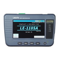
⑨ 4.3 Inch Color Display Capacitive touch panel.
⑩ Line State LED
Indicating the logical status of signal lines on the
target interface.
⑪ Power LED
Lighting in green when using. Blinking in red when
charging battery.
⑫ Keypad Entering commands and other operation.
⑬ Battery Cover Open/close when replacing the battery.
⑨
②
⑧ ⑦
⑤
⑥
⑩
⑫
⑪
⑬
①
③
④
 Loading...