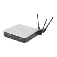
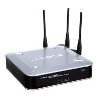
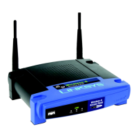
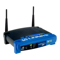
Wireless-G Access Point
Chapter 4: Connecting the
Wireless-G Access Point
1. Locate an optimum location for the Access Point. The best place for the
Access Point is usually at the center of your wireless network, with line of
sight to all of your mobile stations.
2. Fix the direction of the antenna. Try to place it in a position which can
best cover your wireless network. Normally, the higher you place the anten-
na, the better the performance will be. The antenna’s position enhances the
receiving sensitivity.
3. Connect a standard Ethernet network cable to the Access Point. Then,
connect the other end of the Ethernet cable to a switch or hub. The Access
Point will then be connected to your 10/100 Network.
4. Connect the AC Power Adapter to the Access Point’s Power port and
plug the other end into an electrical outlet. Only use the power adapter
supplied with the Access Point. Use of a different adapter may result in
product damage.
Now that the hardware installation is complete, proceed to Chapter 5: Setting
Up the Wireless-G Access Point for directions on how to set up the Access
Point.
5
Instant Wireless
®
Series
4
Note: In order for all other wireless devices to communicate with
the Access Point, those devices must be operating in
Infrastructure Mode. If any wireless devices are configured in
Ad Hoc Mode, they will not be recognized by the Access Point.
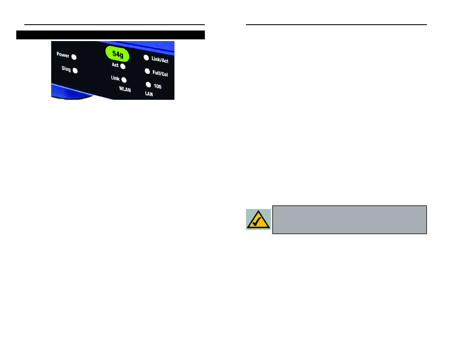
T
Power Green. The Power LED lights up when the Access Point is
powered on.
Diag Red. The Diag LED indicates the Access Point’s self-diagnosis
mode during boot-up and restart. It will turn off upon com-
pleting the diagnosis. If this LED stays on for an abnormally
long period of time, refer to the Troubleshooting Appendix.
WLAN Act Green. If the WLAN’s Act LED is flickering, the Access Point
is actively sending or receiving data to or from one of the
devices on the network.
WLAN Link Green. The WLAN’s Link LED lights whenever there is a suc-
cessful wireless connection.
LAN Act/Link Green. The LAN’s LINK LED serves two purposes. If the
LED is continuously lit, the Access Point is successfully con-
nected to a device through the LAN port. If the LED is flick-
ering, it is an indication of any network activity.
LAN Full/Col Green. The LAN’s Full/Col LED also serves two purposes.
When this LED is continuously lit, the connection made
through the corresponding port is running in Full Duplex
mode. A flickering LED indicates that the connection is expe-
riencing collisions. Infrequent collisions are normal. If this
LED blinks too often, there may be a problem with your con-
nection. Refer to the Troubleshooting Appendix if you think
there is a problem.
LAN 100 Orange. The LAN’s 100 LED indicates when a successful
100Mbps connection is made through the LAN port.
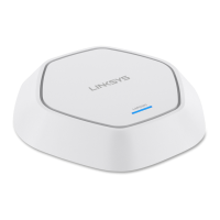
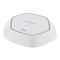
The Wireless-G Access Point’s Front Panel
Figure 3-2
 Loading...