6
lippert.com 432-LIPPERT (432-547-7378) Rev: 08.29.22
Quick Drop Stabilizer
Installation and Owner’s Manual
(For Aftermarket Applications)
CCD-0004455
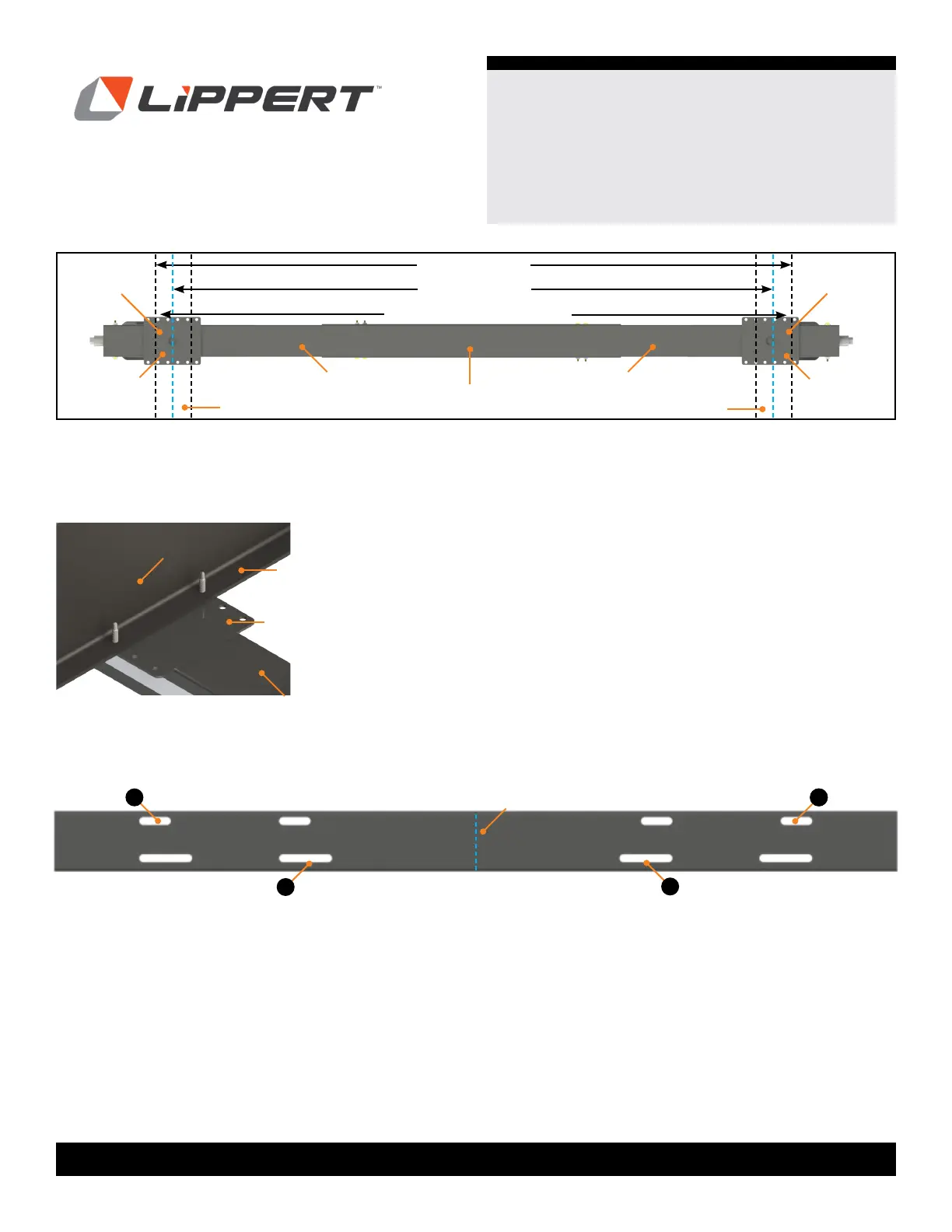
Fig.6
NOTE: It is important to utilize similar slot configurations
on both side of the center piece.
NOTE: Use the same mounting bracket holes on each
side.
5. Gather Quick Drop Stabilizer Double Kit parts on a work
bench/table.
A
A
B
B
Fig.5
Left
Stabilizer
Right
Stabilizer
Center Piece
Overall width
Frame
Frame
Web to Web
Needed measurement
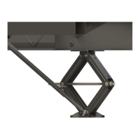
Fig.7
Mounting
Bracket
Mounting
Bracket
Flange
(to attach)
Flange
(to attach)
NOTE: Figures 5 and 6 shown for reference for better
clarity.
Web of frame
Flange
Mounting Bracket
Quick Drop
4. Depending on the length of the width measurement
needed, there are two sizes the slots on the center piece
channel can accommodate: Wide and Short.
A. Wide. The slots towards the ends of the stabilizers
(farthest away from center) refer to the
Wide Positioning (Fig. 7A).
• Inside of I-Beam flange, 61”
• Outside of I-Beam flange, 76”
B. Short. The slots more inward to the center are the
Short Positioning (Fig. 7B).
• Inside of I-Beam flange, 49
5/8”
• Outside of I-Beam flange, 64 5/ 8”
Center