8
lippert.com 432-LIPPERT (432-547-7378) Rev: 08.29.22
Quick Drop Stabilizer
Installation and Owner’s Manual
(For Aftermarket Applications)
CCD-0004455
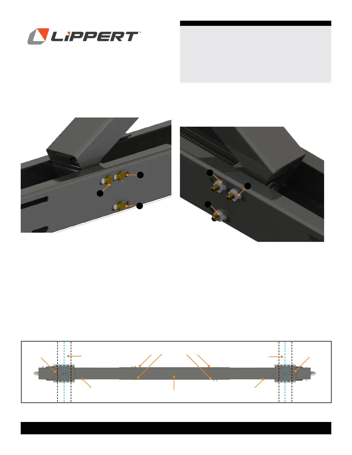
Fig.11
A
A
A
A
A
A
Fig.12
9. Re-insert bolts (Fig. 11A) pushing the T.A.R. pin back out.
NOTE: Figure 11 is the opposite side of the stabilizer.
10. Use new
¼" nylon locking ange nuts (Fig. 12A) to
secure in place, but do not completely tighten as further
adjustments may be necessary during mounting to the
frame.
11. Repeat steps to attach other stabilizer to the opposite
end of the center piece.
12. Adjust legs in the center piece so the mounting holes
desired on the mounting plate coincide with the fastening
location on the outer anges of the left and right I-beams.
13. Tighten nuts and bolts.
NOTE: Do not over tighten bolts as this can cause system
binding. Tighten bolts just until sheet metal starts to bow in.
Center Piece
Frame
Frame
Mounting
Bracket
Mounting
Bracket
Left
Stabilizer
Right
Stabilizer
Fastening Points
NOTE: Figure 13 shows fastening points referred to in
Figures 11 and 12 and Steps 9 to 13.
Fig.13