Rev: 05.20.2022 Page 14 CCD-0001745
Hall Effect Jack Replacement
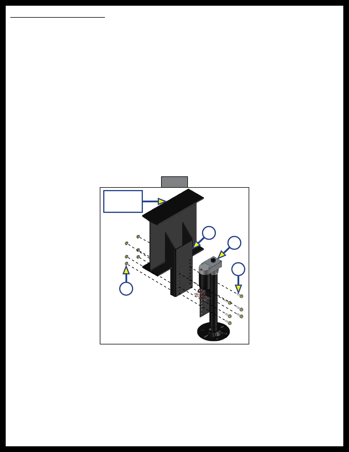
1. Mark mounting location on the bracket of the jack needing replacement.
2. Disconnect jack motor wires from the system's wire harnesses.
3. Remove the jack from its mounting bracket.
4. Install the new jack (Fig. 18C) onto the mounting bracket (Fig. 18B), in the same location previously
identified in step 1, using six
½"
- 20 UNF serrated flange Grade 8 bolts (Fig. 18D) and
½"
- 20 UNF serrated
flange nuts (Fig. 18A). Torque bolts to 90 ft-lbs.
NOTE: Make sure the new jack is mounted in the same location as the old, removed jack (step 3).
5. Reconnect the wire harnesses to the jack motor wires.
NOTE: LCI recommends zip-tying the harnesses tight against the rear jack motors to prevent damage to
the harnesses.
When components are added or replaced, the system will need to be homed.
1. Run the system by pressing the FRONT button (Fig. 1G).
A. A special jack error code should occur.
B. If not, introduce the special jack error code.
I. To introduce an error, disconnect one of the hall effect sensor wires from the controller.
II. After attempting to operate the disconnected jack, the touchpad screen will display an error.
III. Reconnect the hall effect sensor wire.
2. To clear the special jack error code, the jacks need to be homed. See Homing Jacks section.
Fig. 18
D
B
C
Main
Frame Rail
A