Rev: 10.23.23 Page 11 CCD-0005481
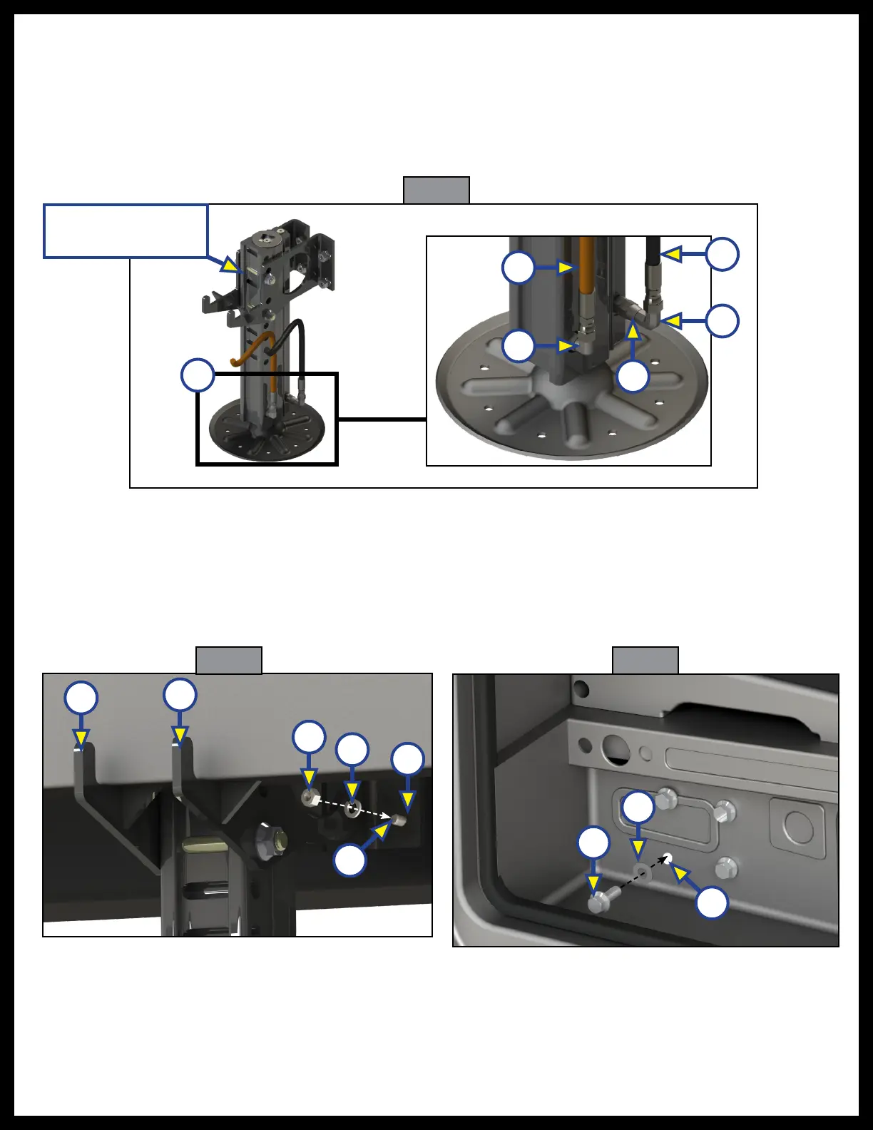
Fig. 14
A
C
B
E
D
F
Passenger side
front jack assembly
4. Position the jack assembly (Fig. 15A) onto the frame rail (Fig. 15B). Clamp or have another person hold
the jack in place, making sure the bolting surface of the mounting brackets line up with the holes
drilled in the frame.
5. From the step well side, insert four 7/16"- 14 x 1 1/4" bolts (Fig. 16A) with 7/16" flat washers (Fig. 16B),
through the hole in the cab wall (Fig. 16C), into the appropriate jack bracket holes (Fig. 15F).
6. At the jack bracket, attach but do not tighten the 7/16" lock washers (Fig. 15D) and nuts (Fig. 15C)
on the four bolts (Fig. 15E).
7. Make sure the jack is straight, and the bracket (Fig. 15A) is tight to the bottom of the frame (Fig. 15B)
before tightening the 7/16" bolts with a 11/16" wrench, 5/8" socket to 50 ft-lbs.
8. Re-install step well cover and trim with original torx screws and tapered plugs.
9. Repeat steps 1-8 for the driver's side.
10. Attach the opposite ends of the extend and retract hoses to the hydraulic pump, see the Hydraulic
Plumbing Diagram section, Figure 51.
Fig. 15 Fig. 16
C
D
F
A
B
A
B
E
C