Rev: 10.23.23 Page 12 CCD-0005481
Rear Jack Bracket and Jack Installation
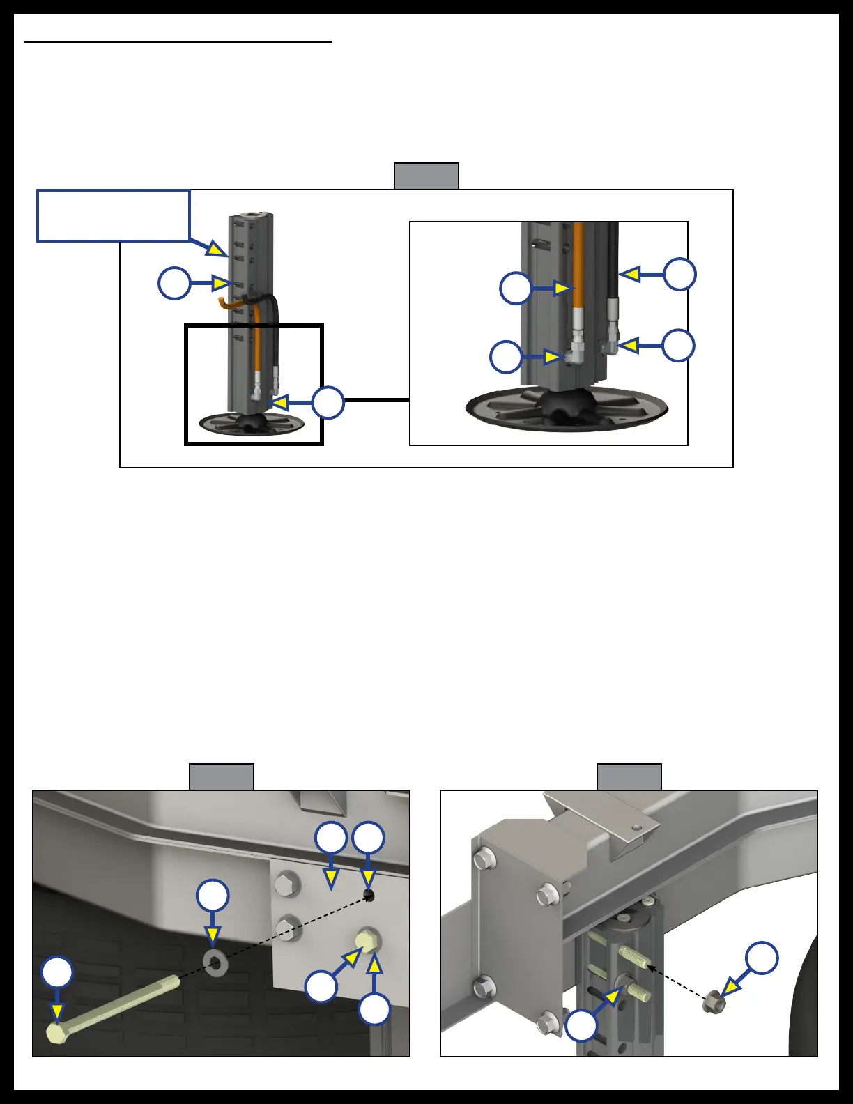
1. Turn the rear jack so that the built-in bracket for the bolts (Fig. 17A) are facing the rear of the coach. At
the bottom of each inside face of the jack (Fig. 17B), remove the retract and extend port plugs and attach
two JIC 90 degree elbow retract fittings (Fig. 17C). Attach the pre-measured orange retract (Fig. 17D)
and black extend hoses (Fig. 17E).
NOTE: Jack brackets can also face the front of the coach, utilizing the front pair of holes in the frame.
Fig. 17
C
C
E
Driver's side
rear jack assembly
NOTE: A recommended minimum ground clearance between the bottom of the jack footpad and the
ground, is 7-9" when the coach is at its maximum rated weight. When installing the jacks on a bare
chassis, keep in mind that some ground clearance will be lost as the coach is built, and to adjust the
installation height accordingly. Make sure that the approach and departure angles are maintained
after the jack is mounted to the jack bracket. Mark the location on both the inside and outside frame
rails that satisfies the minimum clearance requirements.
2. At the appropriate height, place the jack assembly up against the inside beam of the extension bracket (Fig 18A).
NOTE: Bolt length may vary depending on OEM frame extension, but must be a grade 8.
3. Insert two 1/2" - 13 x 8" bolts (Fig. 18B) with 1/2" flat washers (Fig. 18C), through the extension and into
the pre-drilled extension jack bracket holes (Fig. 18D).
4. Attach 1/2" - 13 lock nut (Fig. 19A) to each bolt and tighten to 90 ft-lbs.
5. Repeat steps 1-4 for the passenger side.
6. Attach the opposite ends of the extend and retract hoses to the hydraulic pump, see the Hydraulic
Plumbing Diagram section, Figure 51.
A
B
D
Fig. 18
A
B
C
D
B
C
Fig. 19
A
A