Rev: 10.23.23 Page 22 CCD-0005481
Installing the Aluminum Crossbars
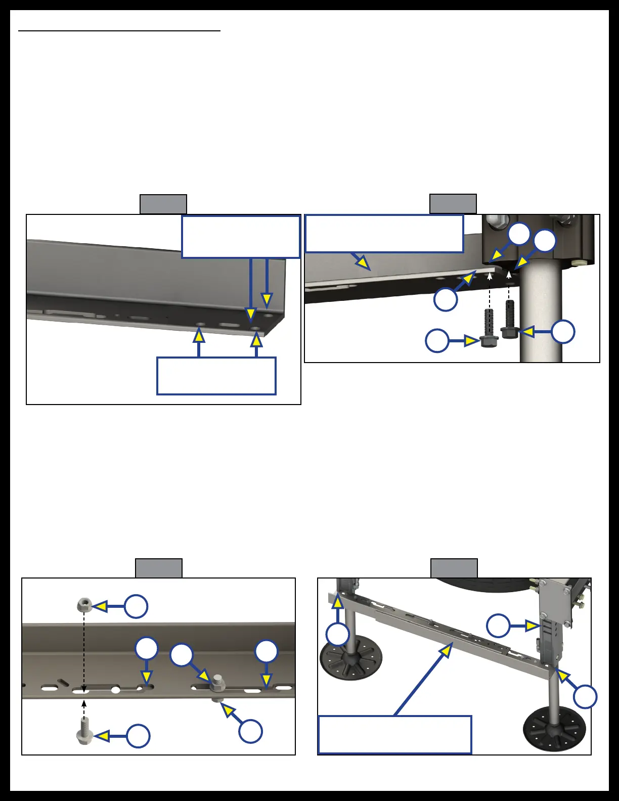
NOTE: Aluminum (shown below) or Steel crossbars are required and mount to the front two jacks.
1. Use two 1/4" - 20 x 1" bolts (Fig. 37C) with two 1/4" - 20 nuts (Fig. 37D) per light. Install the bolt through
the holes in the ends of the lights, into the crossbars and attach the nuts. Do this for each side of
both crossbars.
2. Lower the jacks at least 3 inches to expose the bottom of the jack cylinder (Fig. 38A).
3. Starting with the front passenger side, align one side of the crossbars (Fig. 38B) to the holes in the
bottom of the jack cylinder (Fig. 38A) using two 5/16" - 18 x 1" bolts (Fig. 38C) through the crossbar and
into the jack.
4. Attach another side of the crossbar to the drivers side jack
Fig. 39 Fig. 40
5. After both ends have been attached to the jacks, spread the brackets on the crossbar assembly so that
the mating surfaces come together (Fig. 39A), then install two 3/8" - 16 x 1" bolts (Fig. 39B) and 3/8" -
16 nuts (Fig. 39C).
6. After both ends have been attached to the jacks, spread the brackets on the crossbar assembly
so that the mating surfaces come together (Fig. 39A), then install two 3/8" - 16 x 1" bolts (Fig. 39B)
and 3/8" - 16 nuts (Fig. 39C).
7. If needed, repeat steps 1-6 for the rear jacks. The rear crossbar will be spread further to reach the bottom
of the jack cylinder holes (Fig. 40A) as the rear jack assembly is rotated 90 degrees so that the jack brackets
(Fig. 40B) face the rear of the coach.
Fig. 37
Fig. 38
A
C
B
B
C
A
A
B
C
C
Rear Crossbar Angle Faces
Rear of Coach
A
B
A
Use these two holes
for the front jacks
Use these two holes
for the rear jacks
Front Crossbar Angle Faces
Front of Coach
A