Rev: 10.23.23 Page 7 CCD-0005481
Hydraulic Power Unit Installation
NOTE: The location where the hydraulic power unit will be installed should be as near center on the coach
as possible. Install the hydraulic power unit in accordance with RVIA Gas Codes, since the hydraulic
power unit connections are not spark proof.
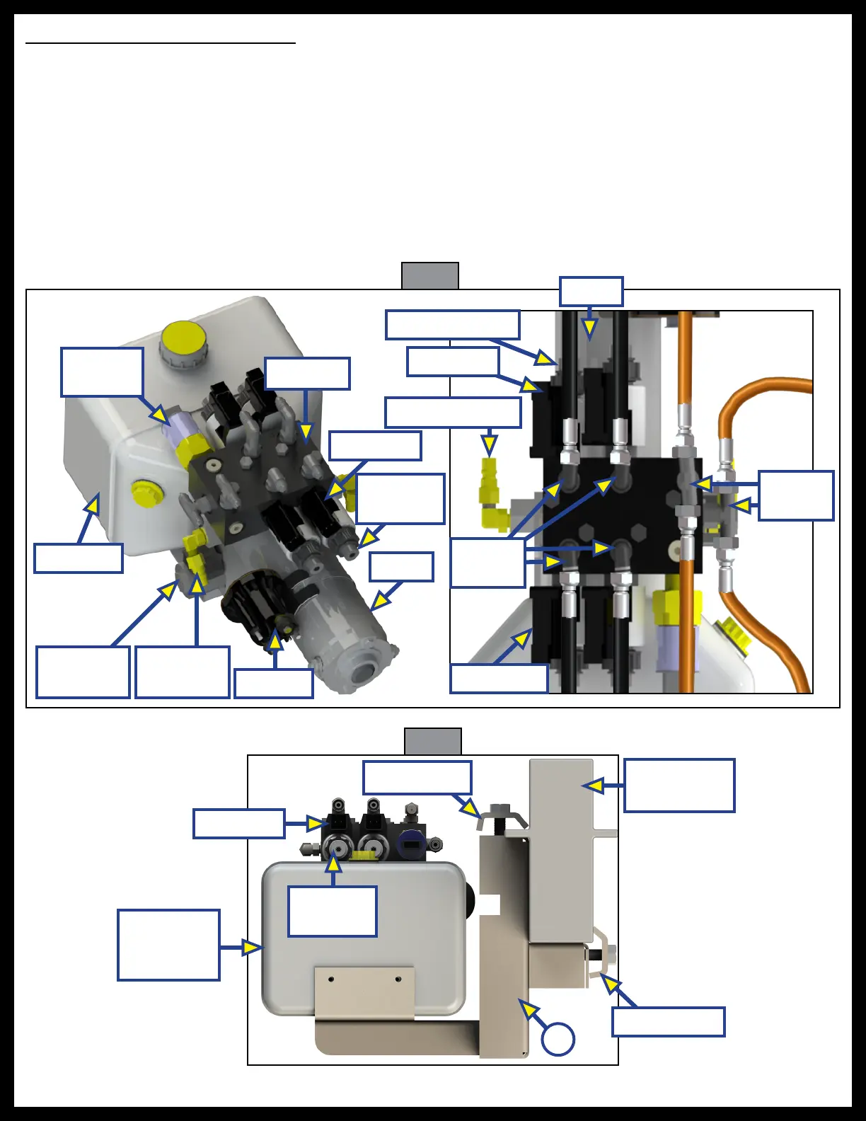
2. Identify the hydraulic power unit mounting location. This will determine the orientation of the
hydraulic fittings (Fig. 6). For this manual, the hydraulic power unit is mounted on the inside driver's
side frame rail, behind the fuel tank.
3. Attach hydraulic power unit bracket assembly (Fig. 7A) to the coach frame using the 7/16"-14 x 4 1/2"
bolts on the outer clamp and the 7/16" - 14 x 2" bolts on the inner clamp (Fig. 7).
4. Bolt the hydraulic power unit to the bracket assembly using the provided manufacturer's screws.
Motor
Frame Rail
Driver Side
A
Outer Clamp
Fig. 6
Fig. 7
Reservoir
Pressure
Switch
Hydraulic
Power Unit
Reservoir
Inner Clamp
Motor
Valve Coil
Solenoid
Quick Disconnect
Retract
Fittings
Cartridge Valve
Valve Coil
Extend
Fittings
Valve Coil
Cartridge
Valve
Manifold
Quick
Disconnect
Directional
Valve
Cartridge
Valve
Valve Coil