Rev: 10.23.23 Page 24 CCD-0005481
Fig. 44
Fig. 45
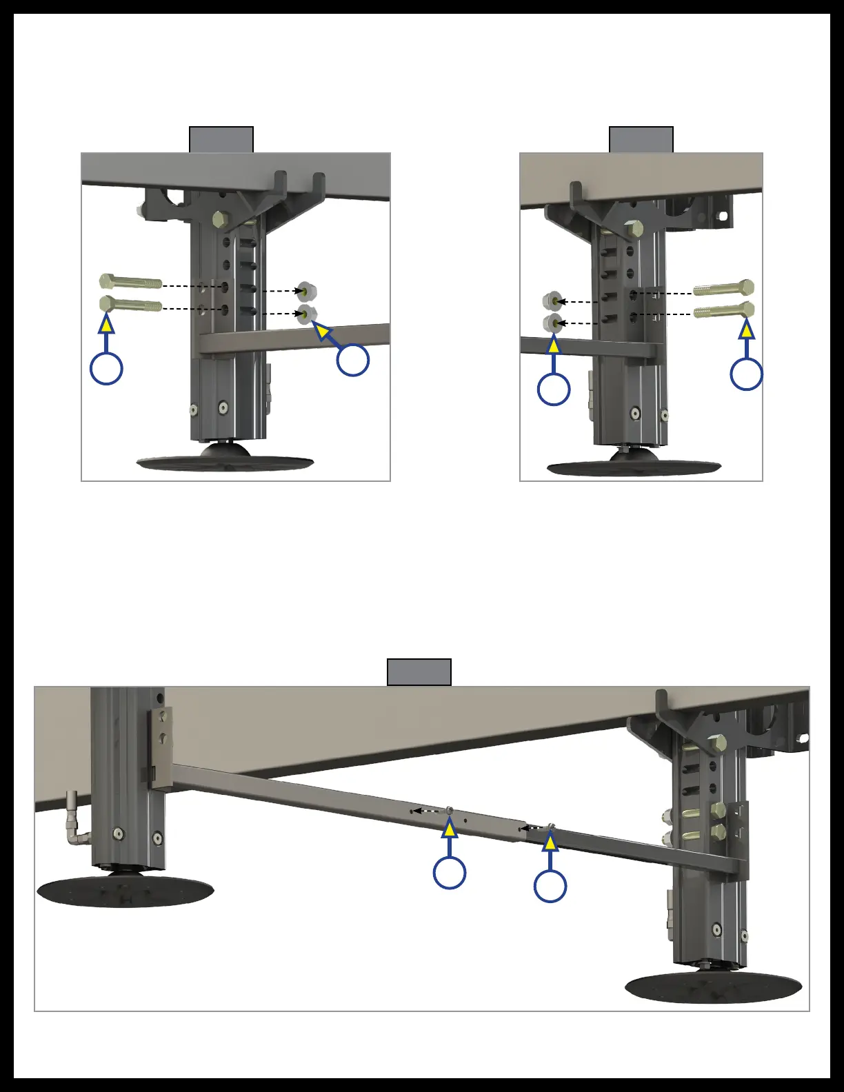
3. Fasten the crossbar bracket curbside to the jack bracket using two 1/2" - 13 x 4" bolts (Fig. 44A) and
1/2" - 13 lock nuts (Fig. 44B). Tighten to 90 ft/lbs. Repeat with the driver's side crossbar bracket and
jack bracket (Fig. 45A, Fig. 45B).
Fig. 46
A
B
A
B
A
A
4. Secure the inner and outer crossbar components together with two 2 1/4" - 14 X 1" self-drilling screws
through the outer most hole options on the outer crossbar shaft (Fig. 46A).
NOTE: Optional 7/16" through hole in cross tie for a 3/8 bolt allowing for a parallel alignment of jacks, or
use provided self tapping screws.