Do you have a question about the Littelfuse Startco SE-325 and is the answer not in the manual?
Explains high-resistance grounding benefits and system types.
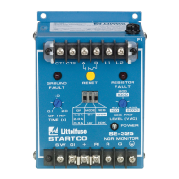
Describes the SE-325's functions and measurement capabilities.
Details adjustable parameters like trip time and trip levels.
Explains adjustment range for ground-fault trip time.
Defines ground-fault trip levels and their relation to resistor ratings.
Differentiates between shunt-trip (SH) and undervoltage (UV) modes.
Explains setting resistor type (20k or 100k) and neutral-to-ground trip voltage.
Describes front panel LEDs and reset functionality.
Specifies the fuse protection for the output contact.
Provides outline, mounting, and connection details for the SE-325 unit.
Details outline, mounting, and connection of the ground-fault current transformer.
Provides outline, mounting, and connection details for sensing resistors.
Covers isolated grounds, overhead lines, and remote operation setup.
Outlines procedures for testing the ground-fault circuit.
Lists detailed electrical and physical specifications for the SE-325.
Lists specifications for various sensing resistor models.
Lists specifications for the CT200 current transformer.
Step-by-step guide for testing ground-fault protection performance.
Outlines tests to verify resistor-fault detection functionality.
Describes how to test the sensing resistor's continuity and resistance.
| Voltage | 120/240 VAC |
|---|---|
| Frequency | 50/60 Hz |
| Reset | Manual or Automatic |
| Current Rating | 5 A |
| Enclosure Rating | NEMA 1 |
| Contact Configuration | SPDT |
| Contact Material | Silver Alloy |
| Alarm Contact | SPDT |
| Trip Contact | SPDT |
| Operating Temperature | -40°C to +60°C |
| Mounting | Panel |