Startco Engineering Ltd. Page 12
SE-325 Neutral-Grounding-Resistor Monitor Rev. 1
Pub. SE-325-M, May 6, 2008.
3.4 ISOLATED-GROUND CONNECTION
The SE-325 is intended for use in installations where the
NGR is connected to local ground. Some installations
require the NGR to be isolated from local ground. See
Technical Information 3.1 “NGR Monitoring with Isolated
Ground Beds” at www.startco.ca.
3.5 O
VERHEAD LINES
In overhead-line applications, atmospheric conditions can
cause false resistor-fault trips. The “S” option or an SE-330
NGR Monitor is recommended for these applications.
3.6 R
EMOTE OPERATION
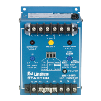
Terminals SW, GI, +, and RI are provided for remote
LED indication and remote reset as shown in Fig. 1.
Remote LED's are driven in series with the front-panel
LED’s.
Remove factory-installed jumpers from terminals GI, +,
and RI, and connect a remote kit as shown in Fig. 1.
Optional remote kits are shown in Figs. 8, 9, and 10.
Standard LED indicator lamps are not compatible with the
SE-325.
For general-purpose applications, use the RK-325 Remote
Indication-and-Reset Assembly or the RK-325I Remote
Indication Assembly. Connect terminals SW, GI, +, and RI
to remote-kit terminals SW, GI, +, and CI/RI.
For 22-mm-component RK-302 applications, connect
terminal X2 of the red ground-fault indicator to GI, terminal
X2 of the red resistor-fault indicator to RI, and connect
indicator X1 terminals to +. For remote reset, connect the
normally open push-button switch across terminals + and
SW.
If indication is required from a separate voltage source, or
if separate ground-fault and resistor-fault contacts are
required, use an RK-13 Relay Interface Module. The
RK-13 mounts on the SE-325 lower terminal block and it is
compatible with the RK-302, RK-325 and RK-325I. See
Figs. 1 and 11. Contact K1 closes when the Ground-Fault
LED is on and contact K2 closes when the Resistor-Fault
LED is on.
3.7 G
ROUND-FAULT TESTING
Use CT-primary current injection to test the ground-fault
circuit. Fig. 12 shows test circuits using the Startco SE-400
Ground-Fault-Relay Test Unit and the SE-100T Ground-
Fault-Relay Tester. The SE-400 has a programmable output
of 0.5 to 9.9 A for a duration of 0.1 to 9.9 seconds. The
SE-100T has LO and HI outputs for 5- and 15-A resistance-
grounded systems.
A test-record form is provided in Section 7 of this
manual. Record the test results and test dates on this form to
meet the requirements of the National Electrical Code
(NEC). Retain the form so that the test data can be made
available to the authority having jurisdiction.
4. TECHNICAL SPECIFICATIONS
4.1 SE-325
Supply:
ac ........................................... 120 or 240 Vac (+10, -50%),
50/60 Hz, 10 VA
ac/dc ...................................... 120 Vdc (+40, -8%), 5 W
or 120 Vac (+10, -29%),
47 to 440 Hz, 5 VA
N
OTE: Voltage between supply terminals (L1, L2) and
ground terminal (G) must not exceed 300 Vac continuous or
1,250 Vac under transient conditions.
Dimensions:
Height.................................... 150 mm (5.9")
Width.................................... 109 mm (4.3")
Depth..................................... 100 mm (4.0")
Shipping Weight....................... 1 kg (2.2 lb)
Environment:
Operating Temperature ........ -40 to 60°C
Storage Temperature ............ -55 to 80°C
Humidity............................... 85% Non-Condensing
Ground-Fault Circuit:
CT Ratio................................ 200:5
CT Input Burden................... 0.02 Ω
Trip Level
(1)
......................... 0.5, 2.0, or 4.0 A
Frequency Response........... 25 to 400 Hz,
25 to 110 Hz with
Option H
Trip Time.............................. 0.1 to 2.0 s,
0.1 to 5.0 s with
Option T
Thermal Withstand
(1)
........... 200 A Continuous,
2,500 A for 2 s
Trip-Level Accuracy ............ +10, -20%
CT Lead Resistance Limit
(2)
0.5 A Trip Level............ 2 Ω
2 A Trip Level............... 5 Ω
4 A Trip Level............... 5 Ω
Trip-Time Accuracy............. 10%
Operating Mode.................... Latching,
Non-latching with
Option N
(1)
Currents referred to primary of CT200 for prospective
ground-fault currents less than 4,000 A.
(2)
Typical maximum CT lead resistance to meet specified
trip level accuracy.
 Loading...