Startco Engineering Ltd. Page 11
SE-325 Neutral-Grounding-Resistor Monitor Rev. 6
Pub. SE-325-M, May 6, 2008.
60.0
(2.36)
44.5
(1.75)
(0.30)
(0.40)
7.7
10.0
96.0
(3.78)
76.0
(3.00)
(0.875)
22.25
28.58
(1.125)
1.25"
CONDUIT
KNOCKOUT
1.70" DIA
3.8 (0.15)
DIA
MOUNTING DETAIL
SIDE VIEW
FRONT VIEW
RESISTOR FAULTRESISTOR FAULT
GROUND FAULTGROUND FAULT
STARTCO
ENGINEERING LTD.
RK-325I
30.0
(1.18)
25.0
(0.98)
CI/RI
+
GI
OUTLINE
NOTES:
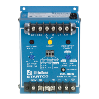
1. DIMENSIONS IN MILLIMETRES (INCHES).
2. NEMA 1.
FIGURE 10. RK-325I Remote Indication Assembly.
60.2
31.0
47.5
21.0
(2.37)
(1.22)
(1.87)
(0.83)
R
S
1
R
S
2
C
G
I
G
R
I
+
S
W
K1 K2
R
S
1
R
S
2
C
G
I
G
R
I
+
S
W
K1 K2
SW CI/GI
+
GI/RI
TB1
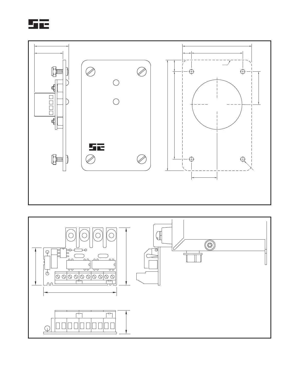
INSTALLATION INSTRUCTIONS:
1. REMOVE FOUR LEFTMOST LOWER TERMINAL BLOCK SCREWS.
2. PLACE RK-13 ON TERMINAL BLOCK AND REPLACE SCREWS.
3. MAKE REQUIRED CONNECTIONS TO TERMINAL BLOCK TB1.
SIDE VIEW
RK-13 SHOWN MOUNTED ON SE-105/SE-107/SE-325
NOTES:
1. DIMENSIONS IN MILLIMETRES (INCHES).
FIGURE 11. RK-13 Relay Interface Module.
 Loading...