Startco Engineering Ltd. Page 5
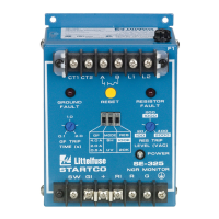
SE-325 Neutral-Grounding-Resistor Monitor Rev. 8
Pub. SE-325-M, May 6, 2008.
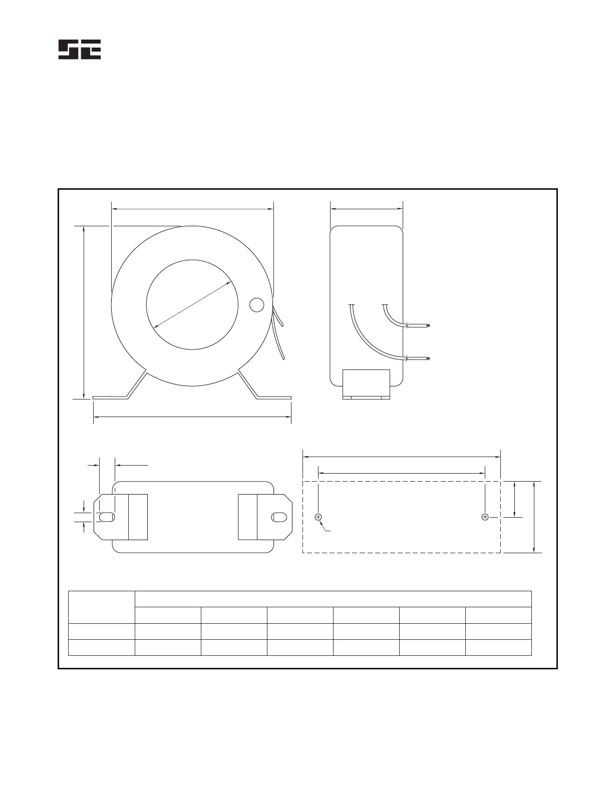
3.2 GROUND-FAULT CT
Outline and mounting details for CT200 and CT200L
current transformers are shown in Fig. 3. Ground-fault-CT
connections and the typical ground-fault-CT location are
shown in Fig. 1.
Connect the secondary of the ground-fault CT to SE-325
terminals CT1 and CT2. The CT connection to the SE-325
is not polarity sensitive. Ground one side of the CT
secondary. For electrically noisy environments or lead
lengths in excess of 10 m (30 ft), use shielded, twisted-pair
cable.
D
A
E
B
FRONT
9.4
(0.37)
F
BOTTOM
B
C
TAP M4 OR 8-32
22.2
(0.87)
44.5
(1.75)
MOUNTING DETAIL
SIDE
WHITE
BLACK
X1
X2
44.5 MAX
(1.75)
NOTES:
1. DIMENSIONS IN
MILLIMETRES (INCHES).
2. MOUNTING SCREWS:
M4 OR 8-32.
PART
NUMBER
CT200
CT200L
A
BCD EF
55.9 (2.20)
88.9 (3.50)
120.7 (4.75)
154.0 (6.06)
101.6 (4.00)
133.4 (5.25)
98.3 (3.87)
139.7 (5.50)
108.0 (4.25)
144.5 (5.69)
5.6 (0.22)
7.1 (0.28)
DIMENSIONS
FIGURE 3. Current Transformers.
 Loading...